APPENDIX D: LVDT OPTION
HF25 DC RESISTANCE WELDING SYSTEM
990-333
D-7
2
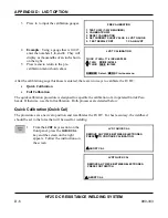
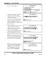
A message will then flash to release the
footswitch. Do so and the screen on
the right appears. Verify the electrodes
are securely installed in the electrode
holders. Place the calibration piece
between the electrodes and press the
footswitch.
LVDT QUICK CAL
PUT THE THICK CALIBRATION GAUGE OF 0.100 in
BETWEEN THE ELECTRODES.
PRESS FOOTSWITCH
V
ABORT CAL
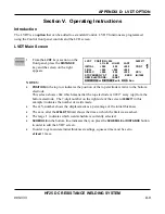
3
NOTE:
if your reference piece is too
thin, or not properly placed between the
electrodes, you will see the prompt at
the bottom of the screen on the left.
QUICK CAL will restart from the
beginning
LVDT QUICK CAL
PIECE MISSING OR TOO THIN – START AGAIN
MENU Previous menu
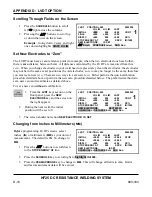
4
Release the footswitch to complete the
quick calibration procedure. The screen
on the right appears briefly then returns
to the LVDT main run screen.
LVDT QUICK CAL
QUICK CAL DONE
−
PLEASE WAIT
V
ABORT CAL
Full Calibration
This procedure does
not
set a new zero point. It merely establishes the calibration for the LVDT. See
Section IV, Operating Instructions, Set New Electrodes to Zero
. Use this procedure on automated
machinery or in cases where the Unitek Peco gauge will not fit between the electrodes. For best
accuracy, the weldhead should be set to the force that will be used for welding.
1
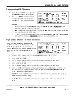
Go to the
MAIN MENU
screen.
MAIN MENU
1. SETUP
5. COMMUNICATION
2. WELD COUNTER
6. RELAY
3. COPY A SCHEDULE
7. CALIBRATION
4. SYSTEM SECURITY
8. RESET TO DEFAULTS
9.
CHAIN
SCHEDULES
NUMBER Select an item
2
Press
7
for
CALIBRATION
which will
bring up the following
CAUTION
screen.
Press the
W
arrow.
CAUTION
CALIBRATION SHOULD BE PERFORMED BY A
QUALIFIED TECHNICIAN ONLY.
REFER TO MANUAL FOR CALIBRATION SETUP.
W
next, MENU menu
Summary of Contents for HF25A
Page 9: ...HF25D DC RESISTANCE WELDING SYSTEM 990 333 ix ...
Page 10: ......
Page 20: ......
Page 84: ...CHAPTER 6 CALIBRATION HF25D DC RESISTANCE WELDING SYSTEM 990 333 6 4 Final Calibration Setup ...
Page 113: ......
Page 129: ......
Page 153: ......
Page 171: ......

