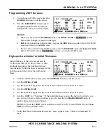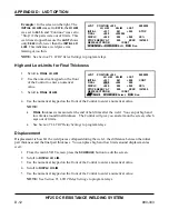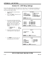
APPENDIX D: LVDT OPTION
HF25 DC RESISTANCE WELDING SYSTEM
990-333
D-9
Section V. Operating Instructions
Introduction
The LVDT is an
option
that can be added to a standard Control. LVDT functions are programmed
using the Control front panel controls and the LCD screen.
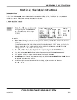
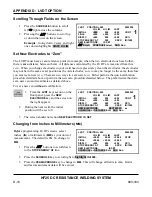
LVDT Main Screen
1
From the
LVDT
keys section on the
front panel, press the
DISTANCE
key and the screen on the right
appears.
NOTES:
LVDT
POSITION
+092 3600277
LO
LIM
HI
LIM
LAST
INITIAL
+000
000
+000
CONT
FINAL
+000
+000
+000
DISPLC
+000
000
+000
XX%
STOP ENERGY AT
000
XXXX
IN/1000
NEW ELECTRODE:
IS SET
SCHEDULE or DISTANCE edit, RUN Run
•
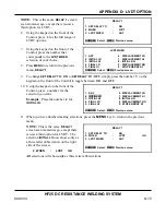
POSITION
in the top row indicates the position of the top electrode relative to the bottom
electrode.
This screen shows
+092
,
which means that the top electrode is 0.092” away (up) from the
bottom electrode. The 7-digit number on the right side of the screen (
3600277
in this
example) indicates the number of welds made.
•
The xx% number shows the displacement as a percentage of the initial thickness
•
The xxxx after the
WELD TO
limit shows the time at which the limit was reached.
•
The large
1
indicates which weld schedule is currently selected.
•
SCHEDULE
in the bottom line indicates that you press the
SCHEDULE or
DISTANCE
button
in order to edit the LVDT screen.
•
In order to get accurate initial thickness readings, squeeze time must be set to
at least
1 msec.
1
Summary of Contents for HF25A
Page 9: ...HF25D DC RESISTANCE WELDING SYSTEM 990 333 ix ...
Page 10: ......
Page 20: ......
Page 84: ...CHAPTER 6 CALIBRATION HF25D DC RESISTANCE WELDING SYSTEM 990 333 6 4 Final Calibration Setup ...
Page 113: ......
Page 129: ......
Page 153: ......
Page 171: ......

