APPENDIX D: LVDT OPTION
HF25 DC RESISTANCE WELDING SYSTEM
D-12
990-333
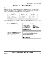
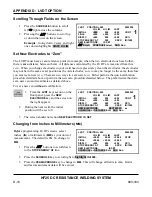
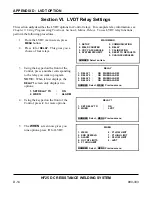
Example:
In the screen on the right, The
INITIAL LO LIM
was set to
037.0
, the
HI LIM
was set to
041.0
, and “Continue” was set to
“Stop” if the parts were out of limits. This
weld was stopped because the
LAST
shows
only
0.022
inch,
lower
than the
INITIAL LO
LIM
. This indicates a weld piece was
LVDT
POSITION
+092 0000000
LO LIM
HI LIM
LAST
INITIAL
+037
041
+022
STOP
FINAL
+000
+000
000
DISPLC
+000
000
+000
XX%
STOP ENERGY AT
000
XXXX
IN/1000
NEW ELECTRODE:
IS SET
SCHEDULE or DISTANCE Edit, RUN Run
missing or too thin.
NOTE:
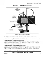
See
Section VI, LVDT Relay Settings
to program relays.
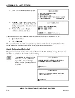
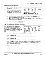
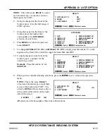
High and Low Limits for Final Thickness
1
Scroll to
FINAL LO LIM
.
2
Use the numerical keypad on the front
of the Control to enter a numerical
value.
3
Scroll to
FINAL HI LIM
.
LVDT
POSITION
+092 0000000
LO
LIM
HI
LIM
LAST
INITIAL
+037
041
+000
CONT
FINAL
+000
+000
000
DISPLC
+000
000
+000
XX%
STOP ENERGY AT
000
XXXX
IN/1000
NEW ELECTRODE:
IS SET
VW
Scroll, SCHEDULE Select, RUN Run
4
Use the numerical keypad on the front of the Control to enter a numerical value.
NOTE:
•
FINAL
thickness is measured at the end of hold time after the weld. You can put high and
low limits around final thickness. The Control will give you an alarm on the screen, which
says out of limits.
•
See
Section VI, LVDT Relay Settings
to program relays.
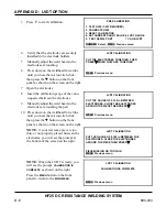
Displacement
Displacement is how far the weld pieces collapsed during the weld – the difference between the initial
part thickness and the final part thickness. You can place high and low limits around displacement as
well.
1
From the main LVDT screen, press the
SCHEDULE
button to edit the screen.
2
Scroll to
DISPLC LO LIM
.
3
Use the numerical keypad on the front of the Control to enter a numerical value.
4
Scroll to
DISPLC HI LIM
.
5
Use the numerical keypad on the front of the Control to enter a numerical value.
NOTE:
See
Section VI, LVDT Relay Settings
to program relays.
Summary of Contents for HF25A
Page 9: ...HF25D DC RESISTANCE WELDING SYSTEM 990 333 ix ...
Page 10: ......
Page 20: ......
Page 84: ...CHAPTER 6 CALIBRATION HF25D DC RESISTANCE WELDING SYSTEM 990 333 6 4 Final Calibration Setup ...
Page 113: ......
Page 129: ......
Page 153: ......
Page 171: ......

