


APPENDIX D: LVDT OPTION
HF25 DC RESISTANCE WELDING SYSTEM
D-14
990-333
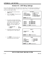
Section VI. LVDT Relay Settings
This section
only
describes the LVDT options for Control relays. For complete relay information, see
Chapter 3, Using Programming Functions, Section I, Menus, Relays.
To use LVDT relay functions,
perform the following procedures.
1
From the LVDT main screen, press
MENU
button.
2
Press
6
for
RELAY
. This gives you a
choice of four relays.
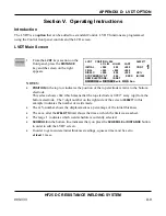
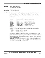
MAIN MENU
1. SETUP
5. COMMUNICATION
2. WELD COUNTER
6. RELAY
3. COPY A SCHEDULE
7. CALIBRATION
4. SYSTEM SECURITY
8. SESET TO DEFAULTS
9.
CHAIN
SCHEDULES
NUMBER Select an item
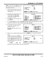
3
Using the keypad on the front of the
Control, press a number corresponding
to the relay you want to program.
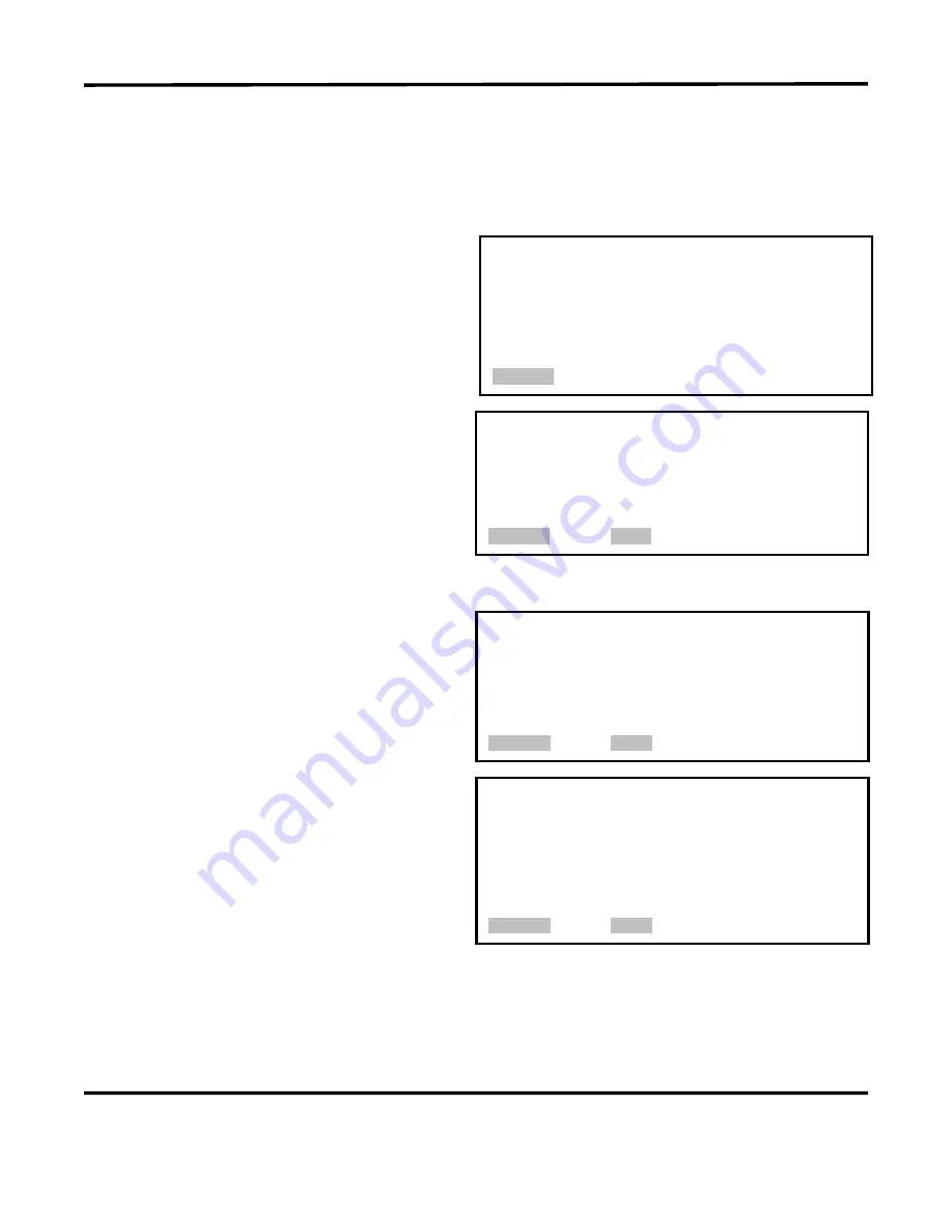
NOTE:
When it first displays, the
RELAY 1
screen only displays two
options:
RELAY
1. RELAY 1 :
ON WHEN ALARM
2. RELAY 2 :
ON WHEN ALARM
3. RELAY 3 :
ON WHEN ALARM
4. RELAY 4 :
ON WHEN ALARM
NUMBER Select, MENU Previous menu
1. SET RELAY TO
:
ON
2. WHEN
:
ALARM
4
Using the keypad on the front of the
Control, press
2
for more options.
RELAY 1
1. SET RELAY TO
:
ON
2. WHEN
:
LVDT
NUMBER Select, MENU Previous menu
5
The
WHEN
screen now gives you
nine options, press
9
for LVDT.
WHEN
1. WELD
6. P1 LOW LIMIT
2. END OF WELD
7. P1 HIGH LIMIT
3. ALARM
8. P2 LOW LIMIT
4. OUT OF LIMITS
9. LVDT
5. P1 HIGH LIMIT
NUMBER Select, MENU Previous menu
Summary of Contents for HF25A
Page 9: ...HF25D DC RESISTANCE WELDING SYSTEM 990 333 ix ...
Page 10: ......
Page 20: ......
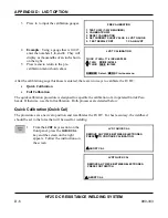
Page 84: ...CHAPTER 6 CALIBRATION HF25D DC RESISTANCE WELDING SYSTEM 990 333 6 4 Final Calibration Setup ...
Page 113: ......
Page 129: ......
Page 153: ......
Page 171: ......


