APPENDIX E. COMMUNICATIONS
HF25D LINEAR DC RESISTANCE WELDING CONTROL
990-333
E-13
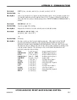
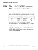
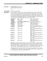
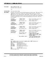
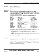
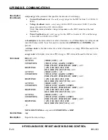
Command
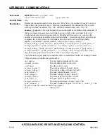
DISP {READ | SET}
<crlf>
[
parameter_name value
<crlf>]
<lf>
Control State
Any except while welding
Description
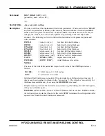
Provides control over the displacement limit check parameters. When used with the "
READ
"
keyword, all parameters pertaining to the currently loaded schedule are returned (see
DISP
under
Control Originated Commands
). When the "
SET
" keyword is used, the host may set
(change) the value of one or more of the parameters pertaining to the currently loaded
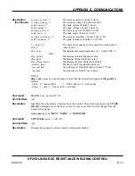
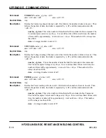
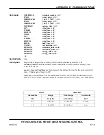
schedule. The following is a list of valid literal substitutions for the parameter_name and
value variables:
INITLO
INITHI
FINALLO
FINALHI
DISPLO
DISPHI
DISPWT
UNITS
INITERR
{
initial_thick_lo
}
low limit for initial thickness
{
initial_thick_hi
}
high limit for initial thickness
{
final_thick_lo
}
low limit for final thickness
{
final_thick_hi
}
high limit for final thickness
{
displacement_lo
}
low limit for final displacement
{
displacement_hi
}
high limit for final displacement
{
displacement_wtd
}
limit for “weld to” displacement
{ IN/1000 | MM }
displacement limit units
{ CONT | STOP }
initial thickness error action
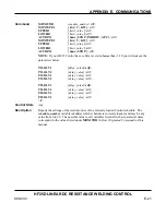
NOTES:
The units of the limit fields parameters depend on the value of the
UNITS
parameter as
follows:
IN/1000:
1 = 0.001 inches; 10 = 0.01 inches
MM:
1 = 0.01 mm; 10 = 0.1 mm
Initial and final thicknesses are positive if the electrodes move farther apart and negative if
they move closer together (in relation to the “zero setting”). The reference “zero setting” for
thickness measurements may be set using the
DISPZERO
command.
Displacement is positive if the electrodes moved closer together during the weld and negative
if they moved further apart.
INITERR
controls the HF25 action if an Initial Thickness limit is reached.
CONT
continues
the weld and gives an alarm at the end of the weld.
STOP
terminates the weld operation after
squeeze time (when the initial thickness is measured).
Summary of Contents for HF25A
Page 9: ...HF25D DC RESISTANCE WELDING SYSTEM 990 333 ix ...
Page 10: ......
Page 20: ......
Page 84: ...CHAPTER 6 CALIBRATION HF25D DC RESISTANCE WELDING SYSTEM 990 333 6 4 Final Calibration Setup ...
Page 113: ......
Page 129: ......
Page 153: ......
Page 171: ......

