APPENDIX E. COMMUNICATIONS
HF25D LINEAR DC RESISTANCE WELDING CONTROL
990-333
E-17
Description
(Continued)
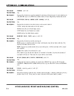
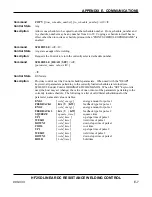
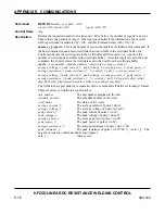
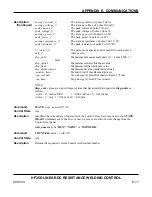
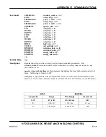
average_current_2:
The average current of pulse 2 (in A).
average_voltage_2:
The average voltage of pulse 2(in mV).
peak_current_2:
The peak current of pulse 2 (in A).
peak_voltage_2:
The peak voltage of pulse 2 (in mV).
average_power_2:
The average power of pulse 2 (in W).
peak_power_2:
The peak power of pulse 2 (in W).
average_resistance_2:
The average resistance of pulse 2 (in 10
-5
Ω
).
peak_resistance_2:
The peak resistance of pulse 2 (in 10
-5
Ω
).
%_control_2:
The percent of capacity control needed to reach pulse 2.
null_2:
Always zero
disp_units:
Displacement measurement units ( 0 = inches/1000, 1 =
mm)
disp_initial:
Displacement initial thickness value
disp_final:
Displacement final thickness value
disp_displacement:
Displacement value (initial minus final)
monitor_limit:
Monitor Limit Time Reached in msec
.
sea_reached:
Stop Energy At Limit Reached (0=False, 1=True)
sea_time:
Stop Energy At Limit Time in msec.
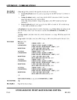
NOTE:
disp_xxxx
values are signed integer values that have units that depend on
disp_units
as
follows:
units = 0 = inches/1000:
1 = 0.001 inches; 10 = 0.01 inches
units = 1 = mm: 1 = 0.01 mm, 10 = 0.10 mm
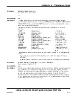
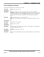
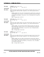
Command
STATE
state_name
<crlf><lf>
Control State
Any
Description
Identifies the current state of operation of the Control. May be in response to the
STATE
READ
Command sent by the host, or may be sent as a result of a state change from the
Control front panel.
state_name
may be "
RUN”,
"
MENU
" or “
MONITOR
”.
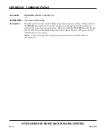
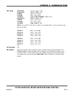
Command
COUNTER
number
<crlf><lf>
Control State
Any
Description
Returns the requested current Control weld counter number.
Summary of Contents for HF25A
Page 9: ...HF25D DC RESISTANCE WELDING SYSTEM 990 333 ix ...
Page 10: ......
Page 20: ......
Page 84: ...CHAPTER 6 CALIBRATION HF25D DC RESISTANCE WELDING SYSTEM 990 333 6 4 Final Calibration Setup ...
Page 113: ......
Page 129: ......
Page 153: ......
Page 171: ......

