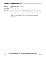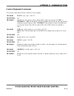
APPENDIX E. COMMUNICATIONS
HF25D LINEAR DC RESISTANCE WELDING CONTROL
E-20
990-333
Description
(Continued)
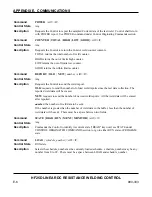
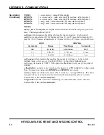
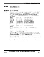
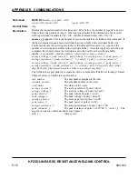
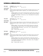
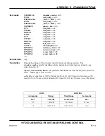
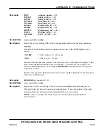
weld_energy
is the parameter that specifies the amount of weld energy.
•
Current Feedback
mode: the
weld_energy
range for the HF25 is from 5 to 2.400A (5-
2400). .
•
Voltage Feedback
mode:
weld_energy
for the HF25 is in units of 0.001 V, and the
range is from 0.200 to 9.9V (200 to 9900).
(Note: Maximum attainable voltage is dependent on the HF25 model and the load
resistance).
•
Power Feedback
mode:
weld_energy
for the HF25 is in units of 1W, and the range
is from 10W to 9900W (10 to 9900).
volt multiplier
is the index value for a table of resistance vs. a PID multiplier for voltage mode
(used for the last weld). Note: Not used in versions where
RINDEXx
and
EINDEXx
are
present.
.
resistance index
is the index value into a table of resistance vs. energy PID tables used for the
last weld.
energy index
is the index value into a PID energy vs. PID values table used for the last weld.
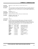
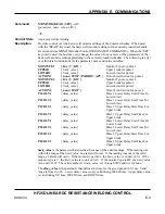
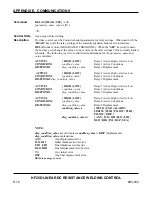
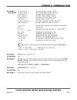
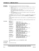
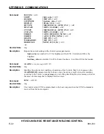
Command
RELAY
<crlf>
ACTIVE1
{ HIGH | LOW }
<crlf>
CONDITION1
{ WELD | END | ALARM | LIMITS
| P1HI | PILOW | P2HI |P2LOW | DISP }
<crlf>
DISPCOND1
{ ANY | ILO | IHI | FLO | FHI
|
DLO | DHI | INI | DSP | WTD }
<crlf>
ACTIVE2
{ HIGH | LOW }
<crlf>
CONDITION2
{ WELD | END | ALARM | LIMITS
| P1HI | PILOW | P2HI |P2LOW | DISP }
<crlf>
DISPCOND2
{ ANY | ILO | IHI | FLO | FHI
|
DLO | DHI | INI | DSP | WTD }
<crlf>
ACTIVE3
{ HIGH | LOW }
<crlf>
CONDITION3
{ WELD | END | ALARM | LIMITS
| P1HI | PILOW | P2HI |P2LOW | DISP }
<crlf>
DISPCOND3
{ ANY | ILO | IHI | FLO | FHI
|
DLO | DHI | INI | DSP | WTD }
<crlf>
ACTIVE4
{ HIGH | LOW }
<crlf>
CONDITION4
{ WELD | END | ALARM | LIMITS
| P1HI | PILOW | P2HI |P2LOW | DISP }
<crlf>
DISPCOND4
{ ANY | ILO | IHI | FLO | FHI
|
DLO | DHI | INI | DSP | SEA }
<crlf>
<lf>
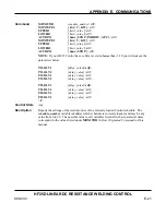
NOTE: DISPCONDx
is only valid if
CONDITIONx
is
DISP
Control State
Any
Description
Reports the relay settings.
Summary of Contents for HF25A
Page 9: ...HF25D DC RESISTANCE WELDING SYSTEM 990 333 ix ...
Page 10: ......
Page 20: ......
Page 84: ...CHAPTER 6 CALIBRATION HF25D DC RESISTANCE WELDING SYSTEM 990 333 6 4 Final Calibration Setup ...
Page 113: ......
Page 129: ......
Page 153: ......
Page 171: ......

