


APPENDIX G: DEFINING THE OPTIMUM PROCESS
HF25D LINEAR DC RESISTANCE WELDING CONTROL
990-333
G-6
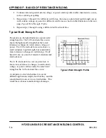
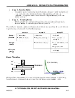
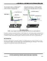
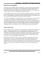
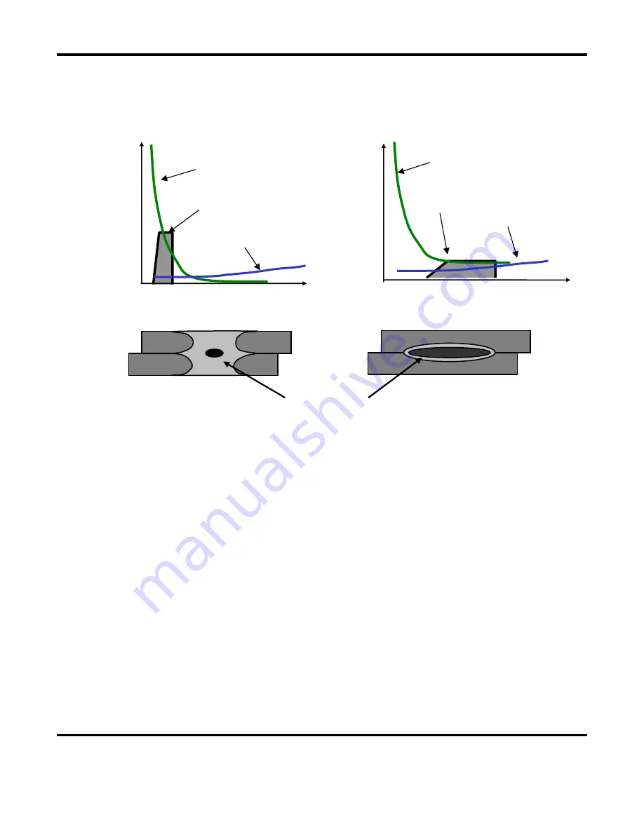
The figure below shows a weld that is fired
early on in the weld sequence when the
contact resistance is still quite high.
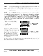
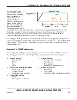
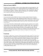
The figure below shows a weld that is initiated
when the contact resistance is lower and in this
example we are using bulk resistance to generate
our weld heat.
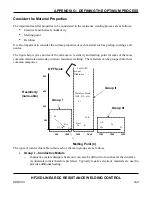
In general conductive materials benefit from a faster heating rate, as the higher contact resistances assist
heat generation in the weld. Resistive materials benefit from slower heating rates that allow the contact
resistances to reduce significantly thus bulk resistances become the major source for heat generation.
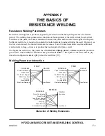
Weld Profiles
The basic welding profile or schedule consists of a controlled application of energy and force over time.
Precision power supplies control the energy, time, and therefore heating rate of the parts. The weld head
applies force from the start to finish of the welding process.
Time
Bulk Resistance
Resistance
Contact Resistance
Weld Pulse
Heat Affected Zone
(NOTE: Larger nuggets are possible with longer weld times when using bulk resistance.)
Resistance
Bulk Resistance
Time
Contact Resistance
Weld Pulse
Summary of Contents for HF25A
Page 9: ...HF25D DC RESISTANCE WELDING SYSTEM 990 333 ix ...
Page 10: ......
Page 20: ......
Page 84: ...CHAPTER 6 CALIBRATION HF25D DC RESISTANCE WELDING SYSTEM 990 333 6 4 Final Calibration Setup ...
Page 113: ......
Page 129: ......
Page 153: ......
Page 171: ......


