CHAPTER 2: INSTALLATION AND SETUP
HF25D DC RESISTANCE WELDING SYSTEM
2-2
990-333
Utilities
Power
Because of the different electrical requirements for the countries in which the Control is used, the
Control is shipped without a power cable connector. The required connections for your power cable
connector are described in
Appendix B, Electrical and Data Connections.
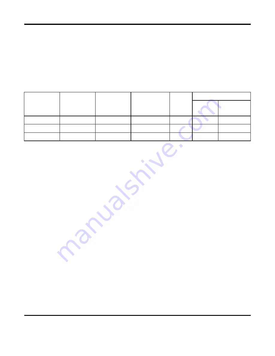
Input power requirements for
the Control are as listed below.
Power Input Specifications
Fuses F1, F2
HF25 Model
Input Voltage,
50-60 Hz,
3 phase
(Vrms)
Ckt Brkr
Current (A rms)
Copper Wire
Gauge,
7 strands (AWG)
Wire Dia
(mm)
Amps/
Volts
Unitek Peco
P/N
HF25A10/240 240
25
10
2.5 6.3 330-096
HF25A10/400 400
20
10
2.5 3.15 330-095
HF25A10/480 480
13
10
2.5 3.15 330-097
Compressed Air and Cooling Water
If you require compressed air and cooling water service for the weld head, please refer to the weld head
manufacturer’s user’s manual for service specifications.
Summary of Contents for HF25A
Page 9: ...HF25D DC RESISTANCE WELDING SYSTEM 990 333 ix ...
Page 10: ......
Page 20: ......
Page 84: ...CHAPTER 6 CALIBRATION HF25D DC RESISTANCE WELDING SYSTEM 990 333 6 4 Final Calibration Setup ...
Page 113: ......
Page 129: ......
Page 153: ......
Page 171: ......

