

CHAPTER 2: INSTALLATION AND SETUP
HF25D DC RESISTANCE WELDING SYSTEM
2-6
990-333
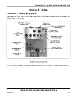
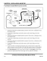
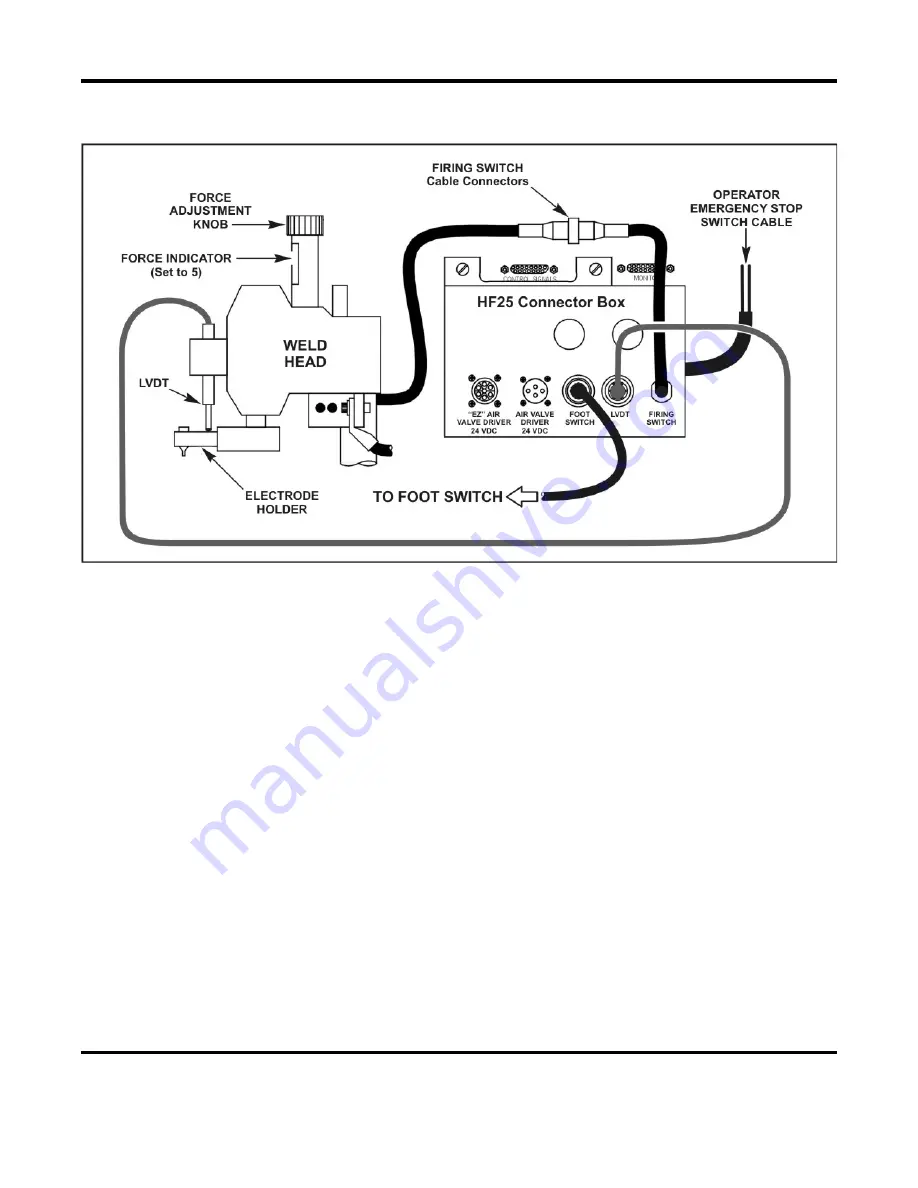
Foot Pedal-Actuated Weld Head Connection
1.
Adjust the weld head force adjustment knob to produce 5 units of force, as displayed on the
force indicator index.
2.
Connect the weld head firing switch cable connector to the Control firing switch cable
connector.
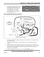
3.
Adjust the weld head force adjustment knob to produce 5 units of force, as displayed on the
force indicator index.
4.
Connect the weld head firing switch cable connector to the Control firing switch cable
connector.
5.
Adjust the weld head force adjustment knob to produce 5 units of force, as displayed on the
force indicator index.
6.
Connect the weld head firing switch cable connector to the Control firing switch cable
connector.
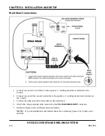
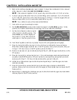
7.
Connect a normally closed, approved, emergency stop switch across the two leads of the
operator emergency stop switch cable. This switch, when operated (open), will immediately
stop the weld cycle. See
Appendix B. Electrical and Data Connections
for circuit details.
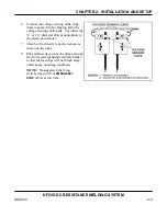
8.
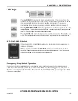
Set the
WELD/NO WELD
switch on the Control front panel to the
NO WELD
position. In this
position, the Control cannot deliver weld energy, but it can control the weld head.
Summary of Contents for HF25A
Page 9: ...HF25D DC RESISTANCE WELDING SYSTEM 990 333 ix ...
Page 10: ......
Page 20: ......
Page 84: ...CHAPTER 6 CALIBRATION HF25D DC RESISTANCE WELDING SYSTEM 990 333 6 4 Final Calibration Setup ...
Page 113: ......
Page 129: ......
Page 153: ......
Page 171: ......


