HF25D DC RESISTANCE WELDING SYSTEM
990-333
iii
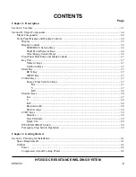
CONTENTS
Page
Chapter 1. Description
Section I: Features .................................................................................................................................. 1-1
Section II: Major Components ............................................................................................................... 1-4
Major
Components
.......................................................................................................................... 1-4
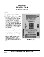
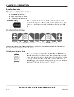
Front Panel Display and Display Controls ...................................................................................... 1-4
Display
..................................................................................................................................... 1-5
Display
Controls
....................................................................................................................... 1-6
SCHEDULE
Selector
Key
................................................................................................ 1-6
Weld Period Selector Keys ............................................................................................... 1-6
Time/Energy
Selector
Keys
.............................................................................................. 1-6
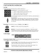
Front Panel Data Entry and Mode Controls ............................................................................. 1-7
Key Pad .................................................................................................................................... 1-7
Numeric
Keys
.................................................................................................................... 1-7
Up/Down
Keys
.................................................................................................................. 1-7
Mode Key ................................................................................................................................. 1-7
RUN
Key
........................................................................................................................... 1-7
MENU
Key
....................................................................................................................... 1-7
Control
Keys
............................................................................................................................. 1-7
Energy
Units
Selection
Keys
............................................................................................. 1-7
KA
.............................................................................................................................. 1-7
V
................................................................................................................................. 1-7
KW
............................................................................................................................. 1-8
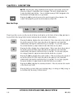
Monitor
Keys
............................................................................................................................ 1-8
KA
..................................................................................................................................... 1-7
V
..................................................................................................................................... 1-8
KW
.................................................................................................................................... 1-8
Resistance
(
Ω
) ................................................................................................................... 1-8
Peak/Average
.................................................................................................................... 1-8
LVDT
Keys
.............................................................................................................................. 1-9
Distance
............................................................................................................................. 1-9
New
Electrode
................................................................................................................... 1-9
Quick
Cal
........................................................................................................................... 1-9
WELD/NO
WELD
Switch
....................................................................................................... 1-9
Emergency
Stop
Switch
Operation
.......................................................................................... 1-9
Chapter 2. Getting Started
Section I: Planning for Installation ........................................................................................................ 2-1
Space
Requirements
......................................................................................................................... 2-1
Utilities
..................................................................................................................................... 2-2
Power
..................................................................................................................................... 2-2
Compressed Air and Cooling Water ......................................................................................... 2-2
Summary of Contents for HF25A
Page 9: ...HF25D DC RESISTANCE WELDING SYSTEM 990 333 ix ...
Page 10: ......
Page 20: ......
Page 84: ...CHAPTER 6 CALIBRATION HF25D DC RESISTANCE WELDING SYSTEM 990 333 6 4 Final Calibration Setup ...
Page 113: ......
Page 129: ......
Page 153: ......
Page 171: ......


