


CHAPTER 3: USING PROGRAMMING FUNCTIONS
HF25 DC RESISTANCE WELDING SYSTEM
3-6
990-333
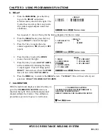
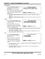
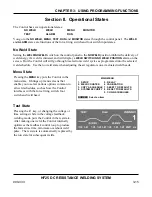
6. RELAY
1.
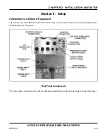
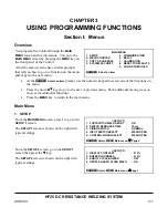
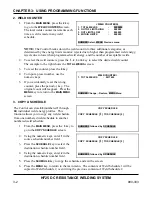
From the
MAIN MENU
, press the
5
key
to go to the
RELAY
output state
selection menu, shown at the right. The
Control has two relays that can provide
dry-contact signal outputs under four
conditions.
<RELAY>
1. RELAY 1
:
ON WHEN ALARM
2. RELAY 2
:
ON WHEN ALARM
NUMBER Select, MENU Previous menu
See
Appendix C, System Timing
for the timing diagrams for the two relays.
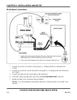
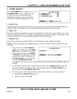
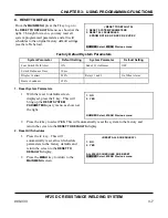
2.
From the
RELAY
menu, press the
1
key
to go to
RELAY
1
shown at the right.
3.
Press the
1
key to toggle the relay
contact signal state:
ON
(closed) or
OFF
(open).
<RELAY 1>
1. SET RELAY TO
:
ON
2.
WHEN
: ALARM
NUMBER Select, MENU Previous menu
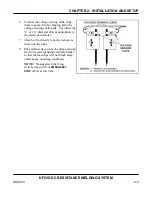
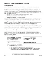
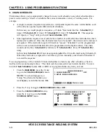
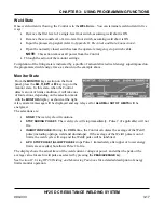
4.
Press the
2
key to select the
WHEN
menu, shown at the right.
5.
Press the
4
key to select
OUT OF LIMITS
as the condition for initiating the Relay
1 output signal. This will bring up the
RELAY 1
menu screen, where the
WHEN
line will now reflect
OUT OF LIMITS
.
WHEN
1. WELD
6. P1 LOW LIMIT
2. END OF WELD
7. P2 HIGH LIMIT
3. ALARM
8. P2 LOW LIMIT
4. OUT OF LIMITS
5. P1 HIGH LIMIT
NUMBER Select, MENU Previous menu
6.
Press the
MENU
key to return to the
RELAY
screen. The
RELAY 1
line will now reflect your
selection:
RELAY 1 ON WHEN OUT OF LIMITS
.
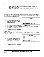
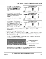
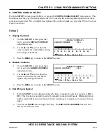
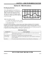
7. CALIBRATION
With the main menu displayed, press the
6
key to
go to the
CALIBRATION CAUTION
screen, as
shown at the right. Only authorized personnel
should calibrate the Control. The calibration
procedure is given in
Chapter 6, Calibration.
< CALIBRATION CAUTION >
CALIBRATION SHOULD BE PERFORMED BY A
QUALIFIED TECHNICIAN ONLY.
REFER TO MANUAL FOR CALIBRATION SETUP.
W
Next, Menu menu
Summary of Contents for HF25A
Page 9: ...HF25D DC RESISTANCE WELDING SYSTEM 990 333 ix ...
Page 10: ......
Page 20: ......
Page 84: ...CHAPTER 6 CALIBRATION HF25D DC RESISTANCE WELDING SYSTEM 990 333 6 4 Final Calibration Setup ...
Page 113: ......
Page 129: ......
Page 153: ......
Page 171: ......


