CHAPTER 3: USING PROGRAMMING FUNCTIONS
HF25 DC RESISTANCE WELDING SYSTEM
3-26
990-333
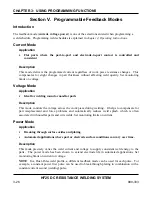
Section V. Programmable Feedback Modes
Introduction
The feedback mode (
current
,
voltage
,
power
) is one of the selections entered when programming a
weld schedule. Programming weld schedules is explained in
chapter 4, Operating Instructions
.
Current Mode
Application
•
Flat parts where the part-to-part and electrode-to-part contact is controlled and
consistent
Description
This mode delivers the programmed current regardless of work piece resistance changes. This
compensates for slight changes in part thickness without affecting weld quality. Set monitoring
limits on voltage.
Voltage Mode
Application
•
Ideal for welding round or non-flat parts
Description
This mode controls the voltage across the work piece during welding. It helps to compensate for
part misplacement and force problems and automatically reduces weld splash, which is often
associated with non-flat parts and wire welds. Set monitoring limits on current.
Power Mode
Application
•
Breaking through surface oxides and plating
•
Automated applications where part or electrode surface conditions can vary over time.
Description
This mode precisely varies the weld current and voltage to supply consistent weld energy to the
parts. The power mode has been shown to extend electrode life in automated applications. Set
monitoring limits on current or voltage.
NOTE
: In a Dual-Pulse weld profile, a different feedback mode can be used for each pulse. For
example, a constant power first pulse can be used to break through plating in combination with a
constant current second (welding) pulse.
Summary of Contents for HF25A
Page 9: ...HF25D DC RESISTANCE WELDING SYSTEM 990 333 ix ...
Page 10: ......
Page 20: ......
Page 84: ...CHAPTER 6 CALIBRATION HF25D DC RESISTANCE WELDING SYSTEM 990 333 6 4 Final Calibration Setup ...
Page 113: ......
Page 129: ......
Page 153: ......
Page 171: ......

