


CHAPTER 3: USING PROGRAMMING FUNCTIONS
HF25 DC RESISTANCE WELDING SYSTEM
990-333
3-27
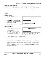
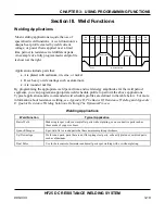
Section VI. Weld Monitor
Introduction
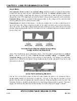
The Control's feedback sensors not only control weld energy output, but they can also be used to
monitor each weld. The Control's monitor features allow you to view graphic representations of welds,
visually compare programmed welds to actual welds, look at peak or average energy values, set upper
and lower limits for welds, and make use of these features:
•
Active Part Conditioner (APC)
•
Energy Limits
•
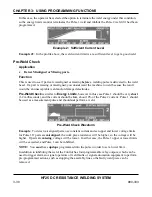
Pre-Weld Check
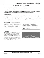
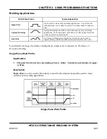
Active Part Conditioner (APC)
Application
•
Displace surface oxides and contamination
•
Reduce contact resistances before delivering the main weld energy.
Description
In the production environment, it is common to see large variations in:
•
Oxide and contamination
•
Plating thickness and consistency
•
Shape and fit up
•
Contact resistances due to varying part fit up
In order for a weld to occur, the surface oxides and contamination must be displaced to allow proper
current flow through the parts. Levels of oxide and contamination vary from part to part over time,
which can have an adverse effect on the consistency of the welding process. If production parts are
plated, there can also be a plating process variation over time resulting in inconsistent welds. These
minor material variations are a major cause of process instability, and it is best welding practice to
seek to minimize their effect.
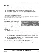
Active Part Conditioner
is designed to cope with material contamination, variation and can be
programmed to apply the exact power to the parts required to displace oxide or contaminants. In
addition, the “Part Conditioner” pulse will terminate at a precise current flow preventing the sudden
high flow, which occurs when the oxide is displaced. This prevents weld splash and material
expulsion, which occurs as a result of an excessively fast heating rate. Part conditioning can help to
reduce variations in contact resistance from part to part caused by different fit up of parts. It will
stabilize the contact resistances before the main welding pulse, therefore reducing variation from
weld to weld.
Summary of Contents for HF25A
Page 9: ...HF25D DC RESISTANCE WELDING SYSTEM 990 333 ix ...
Page 10: ......
Page 20: ......
Page 84: ...CHAPTER 6 CALIBRATION HF25D DC RESISTANCE WELDING SYSTEM 990 333 6 4 Final Calibration Setup ...
Page 113: ......
Page 129: ......
Page 153: ......
Page 171: ......


