CHAPTER 3: USING PROGRAMMING FUNCTIONS
HF25 DC RESISTANCE WELDING SYSTEM
3-28
990-333
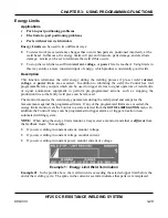
How It Works
Both
constant current
feedback and
constant voltage
feedback modes are limited in their ability
to deal with varying levels of part contamination and oxide. If
constant current
feedback were
used, the power supply would ramp the voltage to very high levels in order to achieve current flow
through the oxide. This rapid input of current is likely to cause splash, especially with round parts.
Constant voltage
mode is not ideal for this purpose either, as the voltage will be restricted from
reaching sufficient levels to break down the oxide.
Constant power
is ideal for this purpose. As the power supply tries to achieve constant power to
the weld, it raises the voltage to high levels early in the output waveform, since current cannot flow
due to the oxide. As the high voltage breaks down the oxide layer, more current flows to the weld
and the voltage and resistance drop. It will achieve this in a controlled fashion to maintain constant
power to the weld.
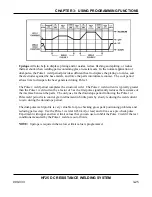
Constant Power Waveform With Corresponding
Voltage And Current Waveforms
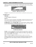
Active Part Conditioning
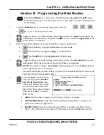
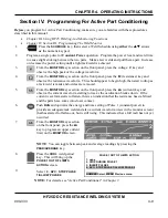
uses a dual-pulse output. The first pulse is programmed for
constant
power
, and the second for either
constant current,
constant voltage
, or
constant power
.
(
Constant voltage
is used if there is still a chance of weld splash). The purpose of a dual-pulse
operation is to enable the first pulse to target displacement of oxides and good fit up; the second
pulse achieves the weld.
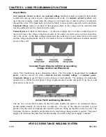
Active Part Conditioning Waveform
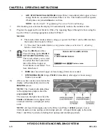
The use of a current limit monitor for the first pulse enables the pulse to be terminated when a
predetermined amount of current flow is achieved. The rise of the current waveform is proof
positive that the oxide is breaking down and the parts are fitting up together, ready to weld. The
first pulse, therefore, should be programmed to be much longer than generally required. The power
supply will terminate the pulse based on the reading of current in the power supply’s monitor.
Summary of Contents for HF25A
Page 9: ...HF25D DC RESISTANCE WELDING SYSTEM 990 333 ix ...
Page 10: ......
Page 20: ......
Page 84: ...CHAPTER 6 CALIBRATION HF25D DC RESISTANCE WELDING SYSTEM 990 333 6 4 Final Calibration Setup ...
Page 113: ......
Page 129: ......
Page 153: ......
Page 171: ......

