


CHAPTER 3: USING PROGRAMMING FUNCTIONS
HF25 DC RESISTANCE WELDING SYSTEM
990-333
3-29
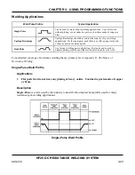
Energy Limits
Applications
•
Part-to-part positioning problems
•
Electrode-to-part positioning problems
•
Parts with narrow weld window
Energy Limits
can be used in two different ways:
•
To detect work piece resistance changes that occur when parts are positioned incorrectly at the
weld head. In this case, the energy limits
will prevent blowouts, parts damage, and electrode
damage. Limits can be set to terminate the weld if this occurs.
•
To stop the weld when a sufficient
current
,
voltage
, or
power
level is reached. Using limits in
this way ensures a more consistent input of energy, which produces consistently good welds.
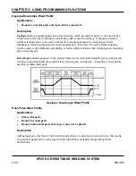
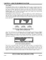
Description
This function terminates the weld energy during the welding process if pre-set weld
current
,
voltage
, or
power
limits are exceeded. In addition to inhibiting the weld, the Control has four
programmable relay outputs which can be used to trigger alarms to signal operators of weld faults,
or signal automation equipment to perform pre-programmed actions, such as stopping the
production line so the faulty weld piece can be removed.
The monitor measures the weld energy parameters during the weld period and compares the
measurements against the programmed limits. If any of the programmed limits are exceeded, the
energy limits monitor sets the Control to a state selected from the
OUT OF LIMITS ACTION
menu. In
addition, the Control's relays can be programmed to trigger alarms, or trigger an action in an
automated welding system.
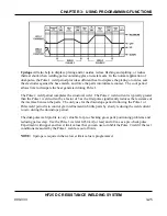
NOTE:
When using the energy limits monitor, always select a monitor mode that is
different
from
the feedback mode. For example:
•
If you are welding in constant current, monitor voltage.
•
If you are welding in constant voltage, monitor current.
•
If you are welding in constant power, monitor current or voltage.
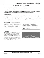
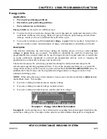
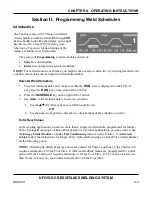
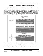
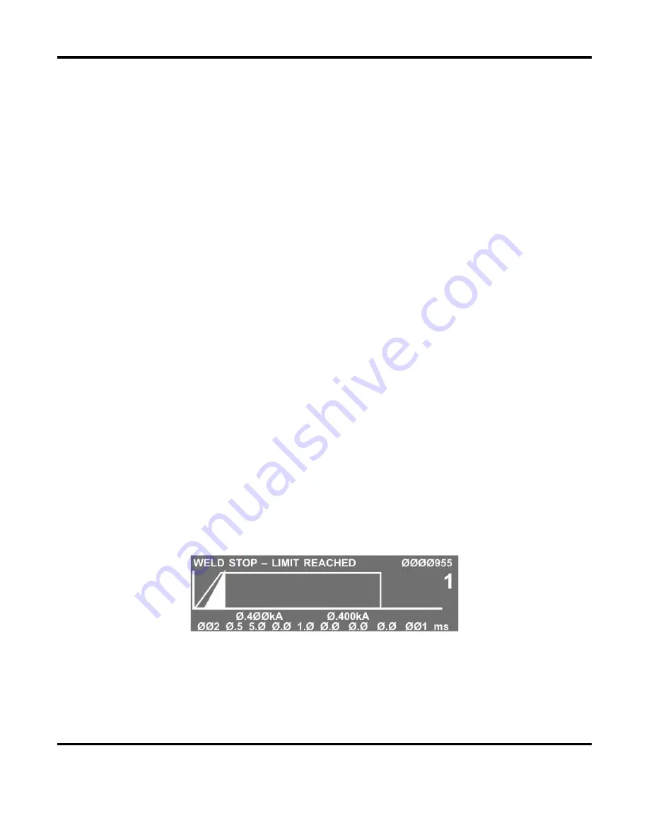
Example 1: Energy Limit Weld Termination
Example #1
: In the profile above, the weld current is exceeding the selected upper limit before the
end of the welding cycle. The spike in the current waveform indicates that parts were misplaced.
Summary of Contents for HF25A
Page 9: ...HF25D DC RESISTANCE WELDING SYSTEM 990 333 ix ...
Page 10: ......
Page 20: ......
Page 84: ...CHAPTER 6 CALIBRATION HF25D DC RESISTANCE WELDING SYSTEM 990 333 6 4 Final Calibration Setup ...
Page 113: ......
Page 129: ......
Page 153: ......
Page 171: ......


