CHAPTER 4. OPERATING INSTRUCTIONS
HF25D DC RESISTANCE WELDING SYSTEM
4-4
990-333
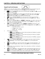
Single-Pulse Weld Schedule
NOTE:
If you are using the optional LVDT, you
must
perform the procedures described in
Appendix
D, LVDT Option, Section 4, Operating Instructions
in
addition
to the procedures below.
1.
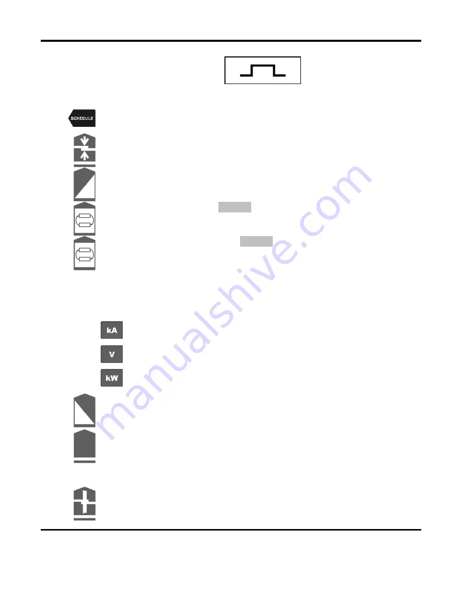
Press the
SCHEDULE
key, then select a Weld Schedule using
either
the
VW
arrows
or
the numeric keypad.
2.
Press the
SQUEEZE
key to enter the squeeze time before the weld. Use the numeric
keypad to enter the time or use the
VW
arrows. Enter a time between
0
and
999
milliseconds.
NOTE
: We recommend 150 milliseconds.
3.
Press the
PULSE 1 UPSLOPE
key to enter the amount of time for the Weld Pulse 1
upslope
. Use the numeric keypad to enter the time or use the
VW
arrows. Enter
0
milliseconds.
4.
Press the
PULSE 1 WELD
key to highlight the
bottom line
of the LCD to enter the weld
time. Use the numeric keypad to enter the time or use the
VW
arrows. Enter a time
between
0
and
99
milliseconds.
5.
Press the
PULSE 1 WELD
key again to highlight the
middle line
of the LCD to enter
weld energy
. Use the numeric keypad to enter the
energy level
or use the
VW
arrows.
The Control output ranges are:
•
Current:
from 0.01
→
2.4 kA
•
Voltage:
0.05
→
9.999 V
•
Power:
0.01
→
9.999 kW
6. Perform
one
of the following:
•
From the
CONTROL
keys section on the front panel, press the
kA
key to program
current
as the feedback mode.
•
From the
CONTROL
keys section on the front panel, press the
V
key to program
voltage
as the feedback mode.
•
From the
CONTROL
keys section on the front panel, press the
kW
key to program
power
as the feedback mode.
7.
Press the
PULSE 1 DOWNSLOPE
key to enter the amount of time for the Weld Pulse 1
downslope
. Use the numeric keypad or the
VW
arrows. Enter
0
milliseconds.
8.
Press the
COOL
key to enter the amount of time for the cool period after Pulse 1. Use
the numeric keypad to enter the time or use the
VW
arrows. Enter
0.5
milliseconds.
9.
Program Pulse 2 by repeating Steps 3 through 7 above using the keys for Pulse 2, entering the
value
0
in each step.
10.
Press the
HOLD
key to enter the amount of time for the hold period after the weld. Use
the numeric keypad or the
VW
arrows. Enter a time between
0
and
999
milliseconds.
We recommend at least
50
milliseconds as weld strength is formed in the hold time.
Summary of Contents for HF25A
Page 9: ...HF25D DC RESISTANCE WELDING SYSTEM 990 333 ix ...
Page 10: ......
Page 20: ......
Page 84: ...CHAPTER 6 CALIBRATION HF25D DC RESISTANCE WELDING SYSTEM 990 333 6 4 Final Calibration Setup ...
Page 113: ......
Page 129: ......
Page 153: ......
Page 171: ......

