CHAPTER 4. OPERATING INSTRUCTIONS
HF25D DC RESISTANCE WELDING SYSTEM
990-333
4-7
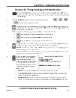
Section III. Programming the Weld Monitor
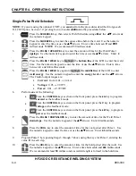
1.
Press the
SCHEDULE
key, then select a Weld Schedule using
either
the
VW
arrows
or
the numeric keypad. Fire the welder and view the output waveform (shaded graph)
on the display.
2. From
the
MONITOR
keys section on the front panel, press the
,
,
,
or
key to view the desired waveform.
3.
Toggle the Pulse 1 weld time/energy selector key to select the
upper
limit field for the
weld period. Use the numeric keypad or the
VW
arrows to enter the
upper limit
value
for the Pulse 1 weld period.
4. Perform
one
of the following to program the Pulse 1 monitor limit mode:
•
Press the
kA
key to program
current
as the limit mode.
•
Press the
V
key to program
voltage
as the limit mode.
•
Press the
kW
key to program
power
as the limit mode.
5.
Toggle the Pulse 1 weld time/energy selector key to select the
lower limit
field for the
weld period. Enter the lower limit value for the Pulse 1 weld period.
NOTE:
In order for a Pulse 1
lower limit
to be programmed, you must
first
program a
Pulse 1 upslope in the weld schedule.
The lower limit mode (current, voltage, or power) will automatically be the same as the
upper limit mode programmed in Step 5.
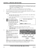
6.
Press the
COOL
weld period key.
This will bring up the
PULSE 1
OUT OF LIMITS ACTION
screen.
This screen allows you to select
the action that the Control will
take if the Pulse 1 upper or lower
limits are exceeded. You have
four
choices:
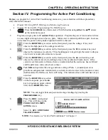
PULSE 1 OUT OF LIMITS ACTION
1. none
2. STOP DURING PULSE 1
3. INHIBIT PULSE 2
4. APC: STOP PULSE 1/ALLOW PULSE 2
NUMBER Select, MENU Previous menu
•
NONE
takes no action if upper or lower energy limits are exceeded.
•
STOP DURING PULSE 1
stops the weld immediately during Pulse 1, and prevents
Pulse 2 from firing (if applicable).
•
INHIBIT PULSE 2
stops the weld at the end of Pulse 1, and prevents Pulse 2 from
firing. This function will not operate if both pulses are joined
without
a cool time.
Summary of Contents for HF25A
Page 9: ...HF25D DC RESISTANCE WELDING SYSTEM 990 333 ix ...
Page 10: ......
Page 20: ......
Page 84: ...CHAPTER 6 CALIBRATION HF25D DC RESISTANCE WELDING SYSTEM 990 333 6 4 Final Calibration Setup ...
Page 113: ......
Page 129: ......
Page 153: ......
Page 171: ......

