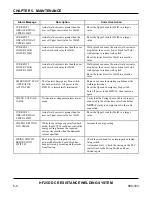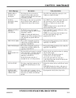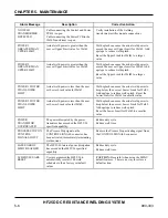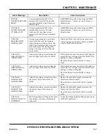
CHAPTER 5. MAINTENANCE
HF25D DC RESISTANCE WELDING SYSTEM
5-2
990-333
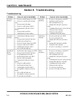
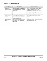
Section II. Troubleshooting
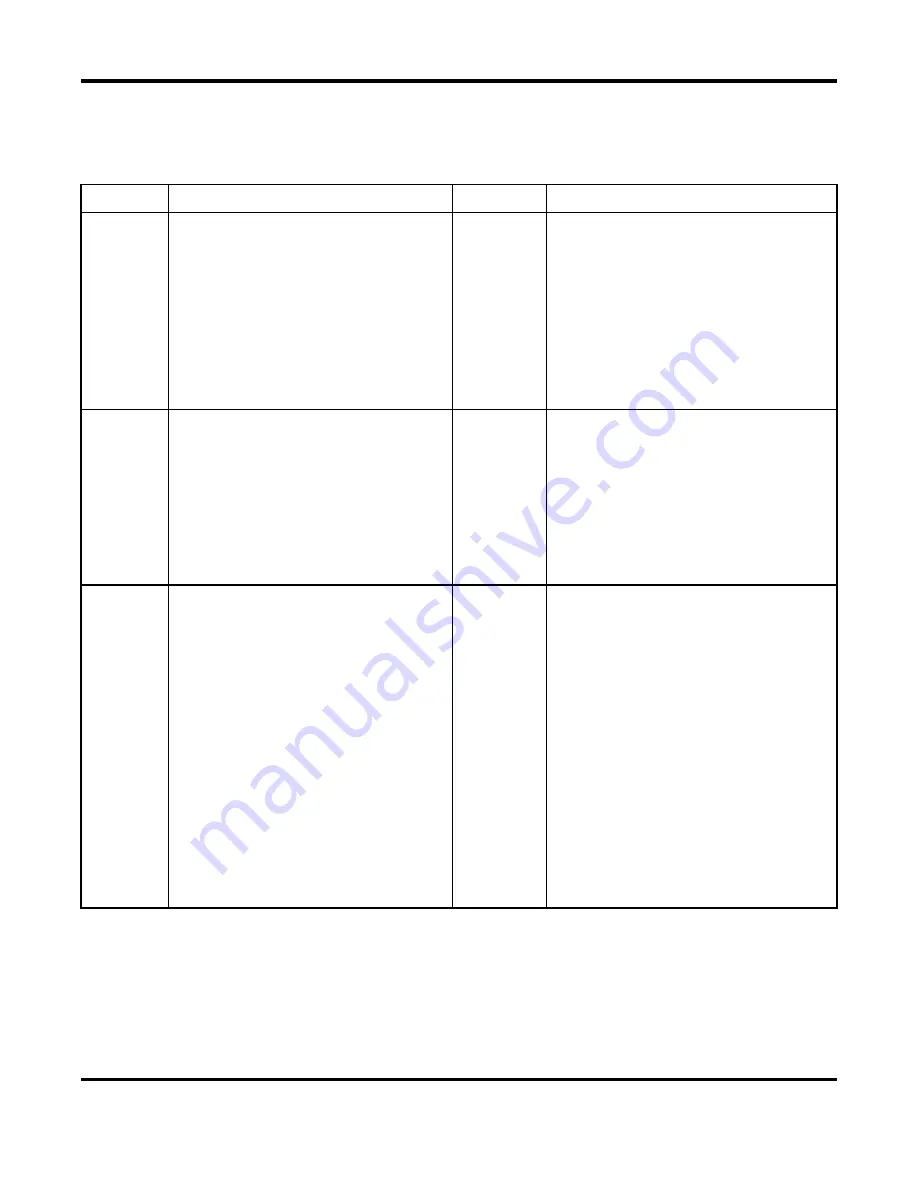
Troubleshooting
Problem
Cause (in order of probability)
Problem
Cause (in order of probability)
Electrode
Damage
1. Excessive current/energy set at HF25
1. Excessive or insufficient weld head
force
1. Wrong electrode tip shape
2. Excessive weld time set at HF25
2. Contaminated weld piece surface/
plating
2. Wrong electrode material
2. Contaminated
electrode surface
Electrode
Sparking
1. Excessive current/energy set at HF25
1. Insufficient weld head force
1. Slow weld head follow-up
1. Incompatible weld piece projection
design
1. Contaminated
weld piece surface/ plating
1. Wrong electrode tip shape
2. Wrong electrode material
2. Contaminated
electrode surface
Electrode
Sticking
1. Contaminated weld piece surface/
plating
1. Wrong electrode material/ tip shape
1. Insufficient weld head force
2. Excessive current/energy set at HF25
2. Excessive weld time set at HF25
2. Contaminated
electrode surface
3. Slow weld head follow-up
Weld Piece
Warping
1. Excessive weld time set at HF25
1. Excessive weld head force
1. Incompatible weld piece projection
design
2. Incompatible weld piece materials
2. Wrong electrode tip shape
3. Excessive current/energy set at HF25
Insufficient
Weld
Nugget
1. Insufficient current/ energy set at HF25
1. Wrong electrode material/ tip shape
1. Worn/mushroomed
electrodes
2. Insufficient weld time set at HF25
2. Incorrect weld head polarity
2. Contaminated weld piece surface/
plating
2. Excessive weld head force
3. Insufficient weld head force
3. Contaminated
electrode surface
3. Incompatible weld piece projection
design
3. Slow weld head follow-up
4. Incompatible weld piece materials
4. No cover gas on weld piece
Metal
Expulsion
1. Excessive current/energy set at HF25
1. Insufficient weld head force
1. Slow weld head follow-up
1. Incompatible weld piece projection
design
2. Contaminated
weld piece surface/ plating
2. Incompatible weld piece materials
2. Contaminated
electrode surface
2. Wrong electrode tip shape
3. No cover gas on weld piece
4. Excessive weld time set at HF25
Summary of Contents for HF25A
Page 9: ...HF25D DC RESISTANCE WELDING SYSTEM 990 333 ix ...
Page 10: ......
Page 20: ......
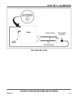
Page 84: ...CHAPTER 6 CALIBRATION HF25D DC RESISTANCE WELDING SYSTEM 990 333 6 4 Final Calibration Setup ...
Page 113: ......
Page 129: ......
Page 153: ......
Page 171: ......

