
APPENDIX B: ELECTRICAL AND DATA CONNECTIONS
HF25D DC RESISTANCE WELDING SYSTEM
B-2
990-333
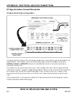
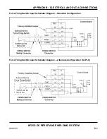
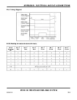
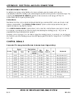
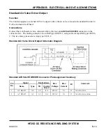
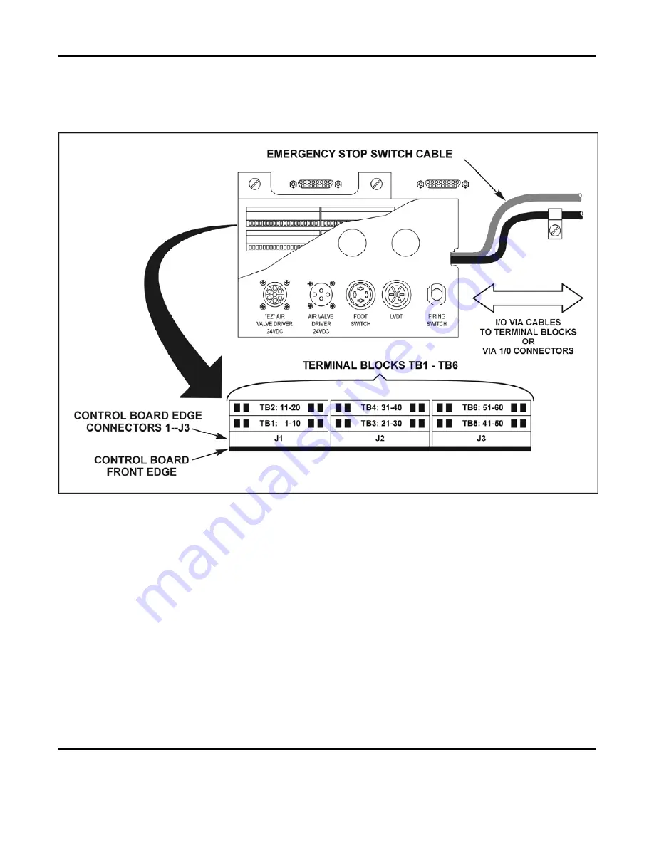
I/O Signal Interface General Description
I/O Signal Interface Physical Organization
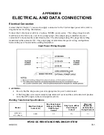
All signals transferred between the Control and external devices enter and leave the unit through the I/O
signal interface. The interface consists of terminal block plugs connected to bulkhead connectors,
CONTROL SIGNALS
and
MONITOR
connectors, and additional connectors (as shown) attached to a
detachable connector box.
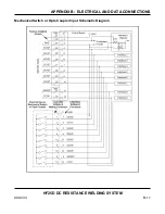
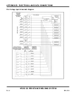
The interface can be used in either of two ways. In the standard form, the Control is shipped with the
connector box in place. Signals are transferred through the interface via the connectors on the connector
box, which are pre-wired to the terminal block plugs. Thus, you have an easy way to attach a weld
head, foot switch, firing switch, and air valve driver to the Control without having to solder or splice
wires.
In the optional form, you can open the connector box and run external device wiring directly into the
interface through the terminal block plugs.
Summary of Contents for HF25A
Page 9: ...HF25D DC RESISTANCE WELDING SYSTEM 990 333 ix ...
Page 10: ......
Page 20: ......
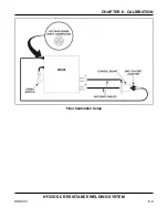
Page 84: ...CHAPTER 6 CALIBRATION HF25D DC RESISTANCE WELDING SYSTEM 990 333 6 4 Final Calibration Setup ...
Page 113: ......
Page 129: ......
Page 153: ......
Page 171: ......


