APPENDIX B: ELECTRICAL AND DATA CONNECTIONS
HF25D DC RESISTANCE WELDING SYSTEM
B-8
990-333
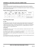
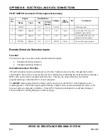
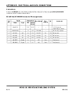
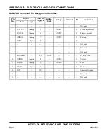
FOOT SWITCH Connector Pin Assignment Summary
Signal Destinations
Pin
No.
Name Type TB
Cntrol
Board
Voltage Max
Current
I/O Comments
1 CGND -- 2-15 J1-15
CGND -- --
Chassis
ground
2
FOOT1
Digital
2-16
J1-16
+24V
10mA
I
Foot switch SW1 (Level 1)
normally open contact
3
FOOT2
Digital
2-17
J1-17
+24V
10mA
I
Foot switch SW2 (Level 2)
normally closed contact
4
FOOTG
Digital
2-18
J1-18
SGND
20mA
I
Foot switch signal ground
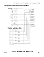
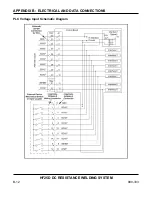
Remote Schedule Selection Inputs
Function
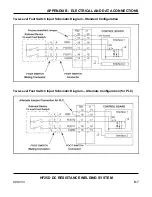
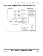
The are two ways to use the remote schedule selection inputs:
•
Schedule Selection Function
•
Schedule Initiation Function
Schedule Selection Function
All weld schedules must be entered and saved to the Control memory locally, through the Control
control panel. Once they are saved, they can be recalled prior to initiating the weld process by placing a
BCD value on the remote schedule selection lines. This may be done with either an external
programmed logic controller (PLC) or host computer.
The
INHIBIT
output signal from the Control can be used to prevent the PLC from beginning a new
welding process. The STOP output signal from the Control can be used to terminate the active weld
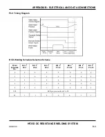
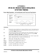
process under an emergency condition. Typical PLC timing in relationship to weld head timing is
shown in the PLC Timing Diagram on the next page.
Summary of Contents for HF25A
Page 9: ...HF25D DC RESISTANCE WELDING SYSTEM 990 333 ix ...
Page 10: ......
Page 20: ......
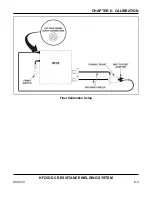
Page 84: ...CHAPTER 6 CALIBRATION HF25D DC RESISTANCE WELDING SYSTEM 990 333 6 4 Final Calibration Setup ...
Page 113: ......
Page 129: ......
Page 153: ......
Page 171: ......

