Installation, Operation and Maintenance Manual
VariCool EZ-Fit
10
Subject to change without notice.
40.20-IM (0118)
Suggested Assembly Sequence
1.
Set Evaporator section in place�
2.
Set Compressor / Condensing section in place�
a.
On Dual Module systems connect the water pipes�
3.
Connect resealable refrigerant fittings.
4.
Attach tie plates
5.
Set Blower section in place�
6.
Attach tie plates�
a.
On Dual Module systems connect the electrical from
one module to the other�
NOTE: If space is limited in the mechanical room it may
be advantageous to suspend the blower section(s)
temporarily as the initial step.
Each module has three or more sections� If the system is
comprised of dual modules, there will be left hand and right
hand sections�
Each section will be labeled as to which system it is� These
labels are typically something such as AC-1, AC-2 or AHU-
1, AHU-2, etc� Make sure when mating up the sections that
each section is correctly matched for the appropriate module�
Additionally, when a dual module system is being assembled
there will also be an indication as to which sections are
left hand (LH) or right hand (RH)� Left and Right hand is
determined when viewing the unit from the control box side
(side opposite the filters).
Each section is also alphabetically labeled so that each
section can be mated properly� Set the sections so that point:
A aligns to A
B aligns to B
C aligns to C
etc�
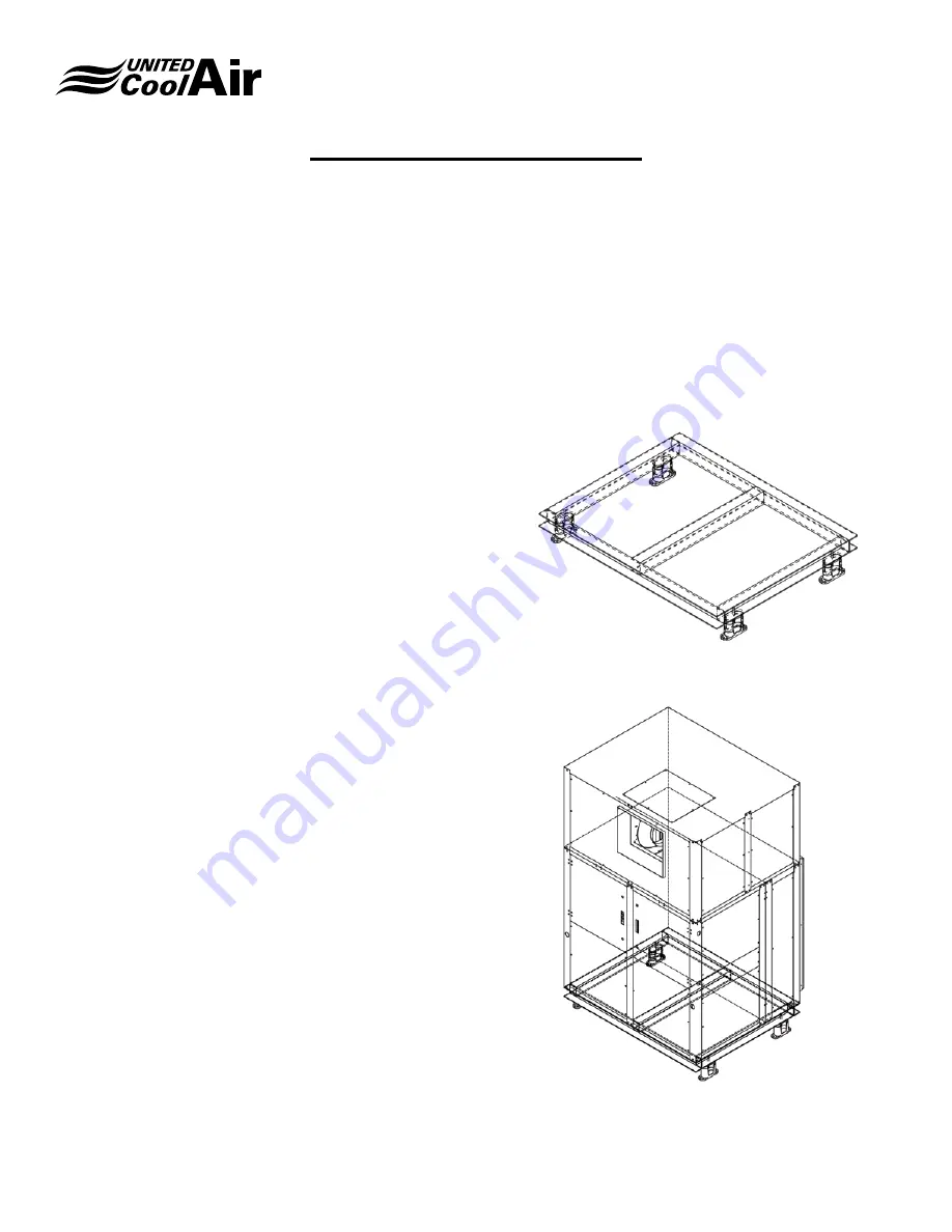
Mounting Options
When installing any floor mounted unit, it is sometimes
desirable to include some form of vibration isolation� Please
note that the unit frames have not been designed for corner
point only loading with vibration isolation methods�
Vibration isolation can be achieved by use of waffle pads
or spring isolation. These are field supplied and applied
accessory items� The selected choice of vibration isolation
should be placed as appropriate in the sequence of
placement of the unit sections�
Please ensure that it is recognized that the ezfit requires
support on the bottom middle of the unit� This means that
corner loading is insufficient for the task of placing an ez fit
unit. The ez-fit requires support on the corners, the middle
of each section, and wherever sections come together� This
observation is critically important, if these methods are not
followed refrigeration pipe breakage will occur and UCA will
refuse warranty of any kind of pipe breakage or leaks if an ez
fit module is not supported by the means supplied herein this
section. The UCA Recommended way is shown on figure 3B
notice where the middle beam supports the mid-section of
the unit�
Figure 3A -Spring Isolation Base
Figure 3B -Unit Positioned On Spring Isolation Base
Mounting and Placement
Summary of Contents for VariCool EZ-Fit 12
Page 2: ......


