DNx-SL-514 Synchronous Serial Interface Board
Chapter 1
7
Introduction
May 2018
www.ueidaq.com
508.921.4600
© Copyright 2018
United Electronic Industries, Inc.
1.6
Device
Architecture
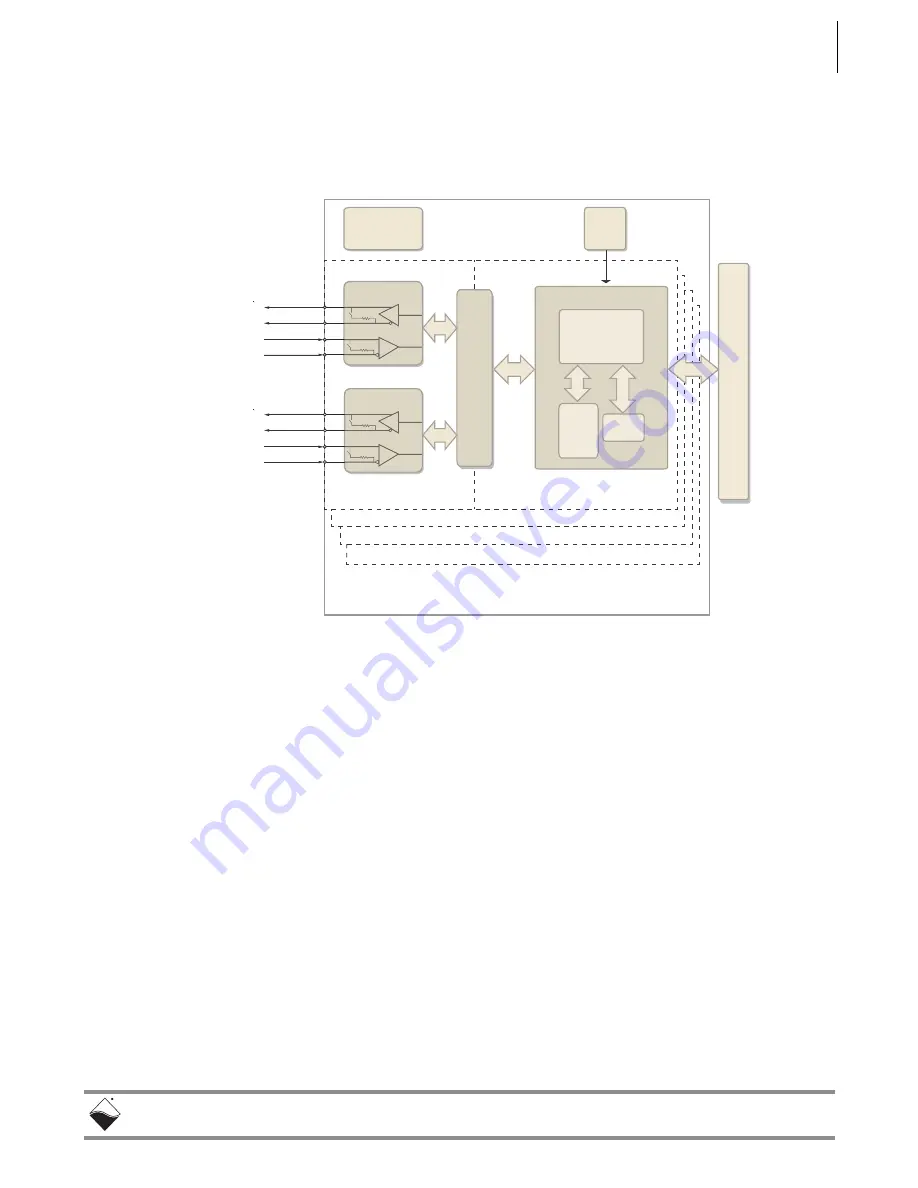
The SL-514 board offers 4 independent synchronous serial interface (SSI)
channels, and each channel provides a master and slave SSI port. All inputs and
outputs are optically isolated and overvoltage protected.
shows a block diagram of the SL-514. Refer to Section 1.8 for pinout.
Figure 1-2 Block Diagram of SL-514
1.7
Device
Description
The SL-514 is a synchronous serial interface (SSI) that supports point-to-point
serial transmissions between a master controller and a slave device.
The SL-514 includes 4 SSI channels, and each SSI channel provides a master
port consisting of differential CLKOUT and DATAIN pins and a slave port
consisting of differential CLOCKIN and DATAOUT pins.
1.7.1
Master/Slave
Device
Description
The SL-514 master device generates an output clock (CLKOUT) at the
user-specified baud rate. Data is received by the master device on DATAIN as
most significant bit (MSB) first, with no particular start or stop sequence required
(no start bit or stop bit).
The slave device receives an input clock on CLOCKIN.The clock transition
causes the slave device to start shifting the serial data word out its slave
transmitter (DATAOUT pin), MSB first.
The data word consists of a user-programmed number of bits, from 3 to 32 bits.
Refer to
.
CHANNEL 3
CHANNEL 2
CHANNEL 1
CHANNEL 0
32-bit 66-MHz Bus
Slave
FIFO
Master
FIFO
SSI
Control Logic
RS-485/422 Tranceiver
100
100
S_CLKIN-
S_DATAOUT-
S_
66 MHz
Internal
Input Clock
RS-485/422 Tranceiver
100
100
M_DATAIN-
M
M_CLKOUT-
M
SLAVE
MASTER
Channel 0 circuitry is repeated for all channels
Optical Isolation
DC/DC
Designed with channel-to-channel and channel-to-chassis isolation
100
100
100
100


