DNA/DNR-429-512/566 ARINC 429 Layer
Chapter 1
13
Introduction
Tel: 508-921-4600
www.ueidaq.com
Vers:
4.5
Date: December 2013
DNx-429-Chap1x.fm
© Copyright 2013
United Electronic Industries, Inc.
1.8.4
Transmitter
Block
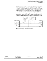
As shown in
Figure 1-2
on page 6, the TX0 transmitter in each Building Block
contains a TX port access controller function, a Scheduler, a TX FIFO, and low-
and high-priority bypass data memory registers. Data is passed from this block
to the ARINC protocol controller and transmitter hardware for transmission to
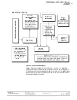
designated receivers. A block diagram of the Hardware Abstraction Layer (HAL)
is shown in
Figure 1-6
.
Figure 1-6. Transmitter Block Diagram (Hardware Abstraction
Layer)
As illustrated in
Figure 1-6
, a transmitter block consists of a Scheduler, two
independent 16-bit prescalers, a 256-word output FIFO, and an emergency
transfer transmitter with a high- and a low-priority register.
The Scheduler transfers its data to the ARINC bus at a specified time interval
either one time or continuously at user-specified intervals. Scheduled data may
also be transferred in blocks based on a “master/slave” entry scheme. Also, the
Scheduler may be configured to transfer data when a predefined label with index
is received from the label filter.
The Prescalers are used to define the time delay for each master entry in the
schedule and may be disabled, keeping entries in the pause state.
Scheduler
(256 entries)
High Priority Data
ARINC HAL
(Hardware Abstraction
Layer) access
engine
Low Priority Data
TX FIFO
(256x32)
TX FIFO Timebase
with “enable”
100 uS
clock
Prescaler 0
(PS0)
with “enable”
Prescaler 1
(PS1)
with “enable”
AR
INC
-429
Ha
rdware Prot
oc
ol
Cont
roller
Timebase selection (100 uS, PS0,
PS1) is specified inside every entry.
Unconditionally triggers the
schedule-enabled “master” and all
related “slave” entries for
transmission over the ARINC-429
bus.
“
Trigger
”
from RX0
label filter


