2
d. See replacement parts list for specifics on kit numbers for
replacement desiccant.
3.
Desiccant regeneration:
a.
— For silica gel (“000”) units:
Pour out used Pink desiccant
onto flat pan. Place Pink desiccant in 350°F (176°C) oven for
approximately three hours or until the desiccant color has
changed back to Blue.
— For 13x molecular sieve (“X00”) units cannot be
regenerated. See page 5 for replacement kits.
— For 4A molecular sieve (“U00”) units: Pour out used
desiccant onto flat pan. Place desiccant in 600°F (316°C)
oven for up to a maximum of 3 hours.
b. Remove desiccant from oven and allow to cool down to ambient
temperature.
c. Pour desiccant back into unit bowl, periodically shaking and
tapping to settle the desiccant.
4. Replace bowl and bowl guard, or metal bowl, and clamp ring onto
the unit. Be sure clamp ring is securely locked in place before
repressurizing the unit.
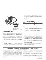
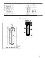
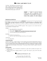
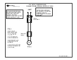
Models X06, X03, X04, and X25
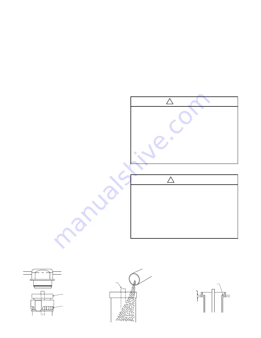
Inner
Step
1/8"
X03 / X04 / X25
Figure 3
Bowl
Clamp
Ring
X03 / X04 / X25
Figure 1
Keep
Covered
Figure 2
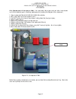
• Coalescing Filter:
Should be used prior to the manual desiccant
dryer in any lubricated compressor system which does not utilize
a system coalescing filter. The coalescing filter removes oil from
the compressed air, which prevents the oil from coating the
silica gel or mole sieve and destroying its ability to dry the air.
Oil contaminated desiccant must be replaced and disposed of
properly, as it cannot be regenerated.
• Afterfilter:
Should be used after the manual desiccant dryer
in any system where any amount of desiccant dust, however
insignificant, is undesirable. The afterfilter prevents the very
slight desiccant dusting, which occurs over time, from proceeding
downstream into the compressed air system.
• Pre-Dryers:
Both the silica gel and mole sieve manual desiccant
dryers can have their drying lives extended through the use of a
pre-dryer. The silica gel (“000”/“M00”) models will typically last
over three times as long if a refrigerated air dryer is placed in the
compressed air system prior to it. (A plant air system refrigerated
dryer will provide the same extended life.) The mole sieve (“U00”/
“MU0”) models will typically last three times as long if a silica gel
(“000”/“M00”) model dryer installed prior to the mole sieve dryer.
(A plant air system desiccant dryer will provide the same extended
life.) Users of either type of manual desiccant dryer who expect
a high air flow demand may wish to consider using a pre-dryer.
Please see page 4 for exact model recommendations.
Operation
1. The silica gel desiccant, when visible through the clear
polycarbonate plastic bowl, contains a color indicator. It changes
from Blue (meaning dry) to Pink (meaning wet) to indicate the need
to replace or regenerate the desiccant. (An X05-02-000 moisture
indicator can be used with 4A molecular sieve units to perform the
same function.) On units with metal bowls, a moisture indicator
mounted on the cover performs the same color changing function.
2. The 4A molecular sieve does not change color. For moisture
indication an X05-02-000 is recommended. See page 4.
3. Environment friendly disiccant changes color from yellow/orange
(meaning dry) to dark green (meaning wet).
3. By installing two or more units in parallel, higher dry airflows can be
achieved.
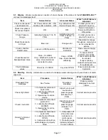
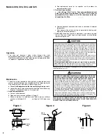
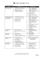
Maintenance
1. The only servicing required for silica gel units is when the desiccant
color or moisture indicator has changed from Blue (meaning dry) to
Pink (meaning wet). Should this color change occur:
a.
Turn off and depressurize the line containing the dryer unit.
b. Loosen the clamp ring and remove the bowl from the top housing.
(Figure 1) Proceed to step 2 or 3, as required.
2.
Desiccant replacement:
a. Pour out used desiccant.
b. Open new container and refill bowl. (Figure 2)
c. Shake or tap bowl to settle desiccant. Add or remove sufficient
quantity to fill Model X03 and X25 unit bowl to 1/8" below inner
step, and for Model X06 fill bowl to within 1/2" of the top. (Figure 3)
!
WARNING
FAILURE OR IMPROPER SELECTION OR IMPROPER USE OF THE
PRODUCTS AND/OR SYSTEMS DESCRIBED HEREIN OR RELATED ITEMS
CAN CAUSE DEATH, PERSONAL INJURY AND PROPERTY DAMAGE.
This document and other information from The Company, its subsidiaries
and authorized distributors provide product and/or system options for further
investigation by users having technical expertise. It is important that you analyze
all aspects of your application, including consequences of any failure and review
the information concerning the product or systems in the current product catalog.
Due to the variety of operating conditions and applications for these products
or systems, the user, through its own analysis and testing, is solely responsible
for making the final selection of the products and systems and assuring that all
performance, safety and warning requirements of the application are met.
The products described herein, including without limitation, product features,
specifications, designs, availability and pricing, are subject to change by The
Company and its subsidiaries at any time without notice.
EXTRA COPIES OF THESE INSTRUCTIONS ARE AVAILABLE FOR INCLUSION
IN EQUIPMENT / MAINTENANCE MANUALS THAT UTILIZE THESE PRODUCTS.
CONTACT YOUR LOCAL REPRESENTATIVE.
!
CAUTION
Polycarbonate bowls, being transparent and tough, are ideal for use with Filters
and Lubricators. They are suitable for use in normal industrial environments, but
should not be located in areas where they could be subjected to direct sunlight,
an impact blow, nor temperatures outside of the rated range. As with most
plastics, some chemicals can cause damage. Polycarbonate bowls should not
be exposed to chlorinated hydrocarbons, ketones, esters and certain alcohols.
They should not be used in air systems where compressors are lubricated with
fire-resistant fluids such as phosphate ester and di-ester types.
Metal bowls are recommended where ambient and/or media conditions are
not compatible with polycarbonate bowls. Metal bowls resist the action of most
such solvents, but should not be used where strong acids or bases are present
or in salt laden atmospheres. Consult the factory for specific recommendations
where these conditions exist.
TO CLEAN POLYCARBONATE BOWLS USE MILD SOAP AND WATER
ONLY! DO NOT
use cleansing agents such as acetone, benzene, carbon
tetrachloride, gasoline, toluene, etc., which are damaging to this plastic.
Bowl guards are recommended for added protection of polycarbonate bowls where
chemical attack may occur.


