


25
WIRING GUIDE FOR 9945
continued...
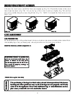
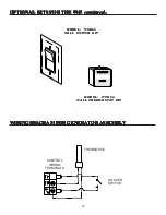
WIRING WITH THE WSK60 - WALL SWITCH KIT:
WIRING WITH THE WSK60 - WALL SWITCH KIT:
WIRING WITH THE WSK60 - WALL SWITCH KIT:
WIRING WITH THE WSK60 - WALL SWITCH KIT:
WIRING WITH THE WSK60 - WALL SWITCH KIT:
PILOT
O
F
F
PILOT
O
N
S
it
E
A
TP TH
TP
TH
ROCKER
SWITCH
CONTROL VALVE
WALL
SWITCH
PIGGYBACK
DISCONNECT
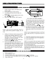
WIRING WITH THE WTK60 - WALL THERMOSTAT KIT AND
WIRING WITH THE WTK60 - WALL THERMOSTAT KIT AND
WIRING WITH THE WTK60 - WALL THERMOSTAT KIT AND
WIRING WITH THE WTK60 - WALL THERMOSTAT KIT AND
WIRING WITH THE WTK60 - WALL THERMOSTAT KIT AND
THE RCK60 - REMOTE CONTROL KIT:
THE RCK60 - REMOTE CONTROL KIT:
THE RCK60 - REMOTE CONTROL KIT:
THE RCK60 - REMOTE CONTROL KIT:
THE RCK60 - REMOTE CONTROL KIT:
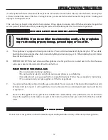
WIRING WITH THE WSK60 - WALL SWITCH KIT AND
WIRING WITH THE WSK60 - WALL SWITCH KIT AND
WIRING WITH THE WSK60 - WALL SWITCH KIT AND
WIRING WITH THE WSK60 - WALL SWITCH KIT AND
WIRING WITH THE WSK60 - WALL SWITCH KIT AND
THE RCK60 - REMOTE CONTROL KIT:
THE RCK60 - REMOTE CONTROL KIT:
THE RCK60 - REMOTE CONTROL KIT:
THE RCK60 - REMOTE CONTROL KIT:
THE RCK60 - REMOTE CONTROL KIT:
Remember the Rocker
Switch must be turned
to "OFF" while using the
Wall Switch.
PILOT
O
F
F
PILOT
O
N
S
it
E
A
TP TH
TP
TH
ROCKER
SWITCH
CONTROL VALVE
REMOTE CONTROL
SENSOR
PIGGYBACK
DISCONNECT
WALL
SWITCH
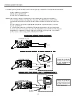
Note: When combining these Optional kits you must remember that only one of them can be used at a time. Example: If
you want to control the operation of this unit with the Remote Control then you must turn the Wall Switch "OFF". When
trying to use two Optional kits at once, one will always override the other.
PILOT
O
F
F
PILOT
O
N
S
it
E
A
TP TH
TP
TH
ROCKER
SWITCH
CONTROL VALVE
REMOTE CONTROL
SENSOR
PIGGYBACK
DISCONNECT
50 60 70 80 90
21
10
32
c
50 60 70 80 90
21
10
32
c
WALL
THERMOSTAT
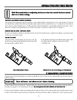
Note: When combining these Optional kits, only one kit can be used at a time. Example: If you want to control the
operation of this unit with the Remote Control then you must turn the Wall Thermostat "OFF". When trying to use two
Optional kits at once, one will always override the other.
For further information, contact our Customer Service Department at United States Stove Company, 227 Industrial Park
Road, P.O. Box 151, South Pittsburg, Tn. 37380. (423)837-2100


