background image

853801C-1804M

INSTALLER: Leave this manual with the appliance.

CONSUMER: Retain this manual for future reference.

Please read this manual BEFORE installing and 

operating this fireplace.

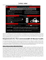
CALIFORNIA PROPOSITION 65 WARNING:

This product can expose you to chemicals including carbon monoxide, which 

is known to the State of California to cause cancer, birth defects and/or other 

reproductive harm. For more information, go to www.P65warnings.ca.gov

Ce produit peut vous exposer à des agents chimiques, y compris au monoxyde de 

carbone, lesquels sont reconnus dans l’État de la Californie comme causant le cancer et 

des malformations congénitales ou autres dommages au fœtus. Pour obtenir plus de 

renseignements, veuillez consulter le site www.P65warnings.ca.gov

• 

Do not store or use gasoline or other flammable vapors and liquids in the vicinity of this or any other appliance.

•  WHAT TO DO IF YOU SMELL GAS

• 

Do not try to light any appliance.

• 

Do not touch any electrical switch; do not use any phone in your building.

• 

Leave the building immediately.

• 

Immediately call your gas supplier from a neighbor’s phone. Follow the gas supplier’s instructions.

• 

If you cannot reach your gas supplier, call the fire department.

• 

Installation and service must be performed by a qualified installer, service agency or the gas supplier.

WARNING:

FIRE OR EXPLOSION HAZARD

Failure to follow safety warnings exactly could result in serious injury, death, or property damage.
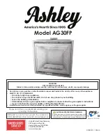
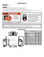
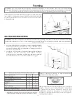
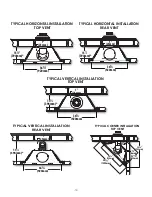
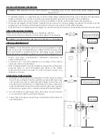
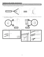
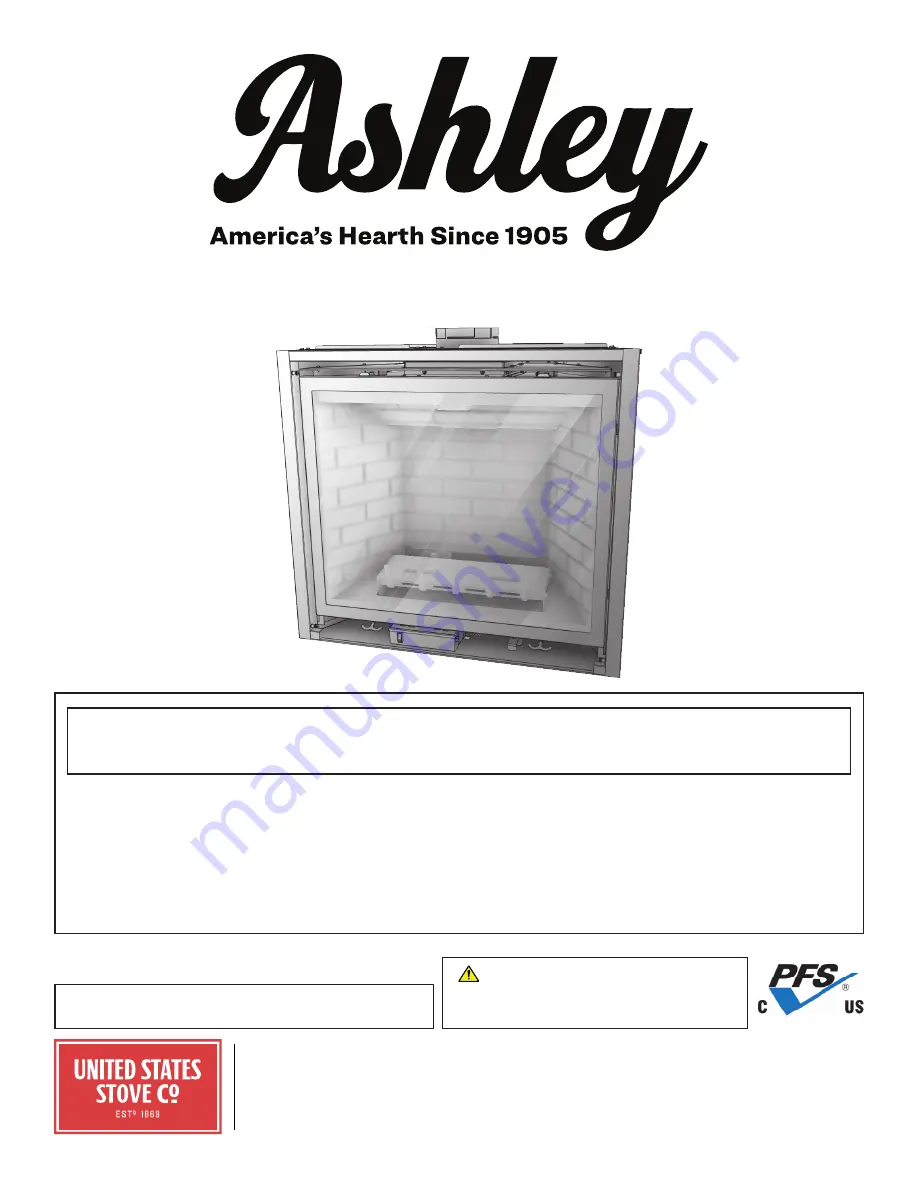
Model AG30FP

United States Stove Company

227 Industrial Park Rd.,

South Pittsburg, TN 37380

PH: (800) 750-2723

www.usstove.com

Report # F18-426R1

Summary of Contents for Ashley AG30FP

Page 1: ...seignements veuillez consulter le site www P65warnings ca gov Do not store or use gasoline or other flammable vapors and liquids in the vicinity of this or any other appliance WHAT TO DO IF YOU SMELL...

Page 2: ...ciency This installation must conform with local codes or in the absence of local codes with the National Fuel Gas Code ANSI Z223 1 NFPA 54 or the Natural Gas and Propane Installation Code CSA B149 1...

Page 3: ...ot B BEFORE smell next to the floor 1 STOP 2 3 4 5 6 the next step 7 8 9 1 2 CAUTION FOR YOUR SAFETY READ BEFORE LIGHTING WARNING If you do not follow these instructions exactly a fire or explosion ma...

Page 4: ...LOW KEEP CLEAR OF ALL OBSTRUCTIONS INSPECTION The state or local gas inspector of the side wall horizontally vented gas fueled equipment shall not approve the installation unless upon inspection the i...

Page 5: ...to a fireplace or stove install an adjustable safety gate to keep toddlers young children and other at risk individuals out of the room and away from hot surfaces 8 Due to high temperatures the applia...

Page 6: ...tedtostone brickandmortar Noncombustibles are safe to overlay the black painted metal face including radiant plates and do not pose a fire hazard Do not allow any noncombustible finish material to ext...

Page 7: ...instructions will void the warranty WARNING This appliance must be vented to the outside The venting system must NEVER be attached to a chimney serving a separate solid fuel burning appliance Each ga...

Page 8: ...our 4 machine screws attaching the draft hood collar to the intake chamber STEP 6 Remove the six 6 machine screws attaching the intake inner draft hood to the firebox inside top Venting REAR VENT APPL...

Page 9: ...ttach the back cover plate to the top of the appliance using the previously removed five 5 machine screws STEP 10 Attach the intake inner draft hood to the firebox back using the previously removed si...

Page 10: ...t conform with venting requirements and restrictions as outlined in this manual Provide a means for visually checking the vent connection to the appliance after it is installed VENT SECTION CLEARANCES...

Page 11: ...o be used a lintel must be used over the top of the fireplace to support the additional weight WARNING Provide adequate clearances around air openings into the combustion chamber Provide adequate clea...

Page 12: ...HORIZONTAL INSTALLATION TOP VENT 36 920mm 1 25mm 15 394mm 1 2 TYPICAL HORIZONTAL INSTALLATION REAR VENT 36 920mm 1 25mm 15 394mm 1 2 TYPICAL CORNER INSTALLATION TOP VENT 50 1280mm 36 920mm 11 301mm 6m...

Page 13: ...tallation instructions for vertical terminations A minimum of 1 25 mm clearance on all sides of the vertical vent pipe must be maintained Attic insulation shields may be insulated using unfaced insula...

Page 14: ...ial used 1 Bend mounting brackets up 90 at perforation as shown Bend Here 90 2 Depending on facing material the lower half of the mounting bracket can be adjusted forward or backward 1 2 13 mm as need...

Page 15: ...nected from the gas supply piping system during any pressure testing of that system at pressures in excess of 1 2 psi 3 5 kPa For test pressures equal to or less than 1 2 psi 3 5 kPa the appliance mus...

Page 16: ...2 1 25 0 38 Over 7 12 to 8 12 1 5 0 46 Over 8 12 to 9 12 2 0 0 61 Over 9 12 to 10 12 2 5 0 76 Over 10 12 to 11 12 3 25 0 99 Over 11 12 to 12 12 4 0 1 22 Over 12 12 to 14 12 5 0 1 52 Over 14 12 to 16 1...

Page 17: ...above if within 10 ft 3 m horizontally Massachusetts 10 ft 3 m L Clearance above paved sidewalk or paved driveway located on public property 7 ft 2 13 m M Clearance under veranda porch deck or balcon...

Page 18: ...are only required if adjustments to the restrictor are needed after the appliance has been installed Restrictor Adjustment Guidelines Flame Appearance Draft Problem Solution Short flickering Excessiv...

Page 19: ...Horizontal Run HMIN Max Horizontal Run HMIN 90 elbow 6 152 mm 4 ft 1 22 m NG LPG Max Vertical Max Horizontal Combination Max Vertical Rise Max Horizontal Run Total Length 10 ft 3 1 m 20 ft 6 1 m 30 ft...

Page 20: ...rtical Venting Minimum Vertical Length Maximum Vertical Length 90 elbow 6 ft 1 83 m 40 ft 12 2 m NG Max Vertical Max Horizontal Combination Maximum Vertical Rise Maximum Horizontal Run Total Length 10...

Page 21: ...ombination Maximum Vertical Rise Maximum Horizontal Run Total Length 10 ft 3 1 m 20 ft 6 1 m 30 ft 9 2 m Maximum number of 90 elbows 5 WARNING Horizontal vent sections require 1 4 6 mm rise for every...

Page 22: ...nce and cause excessive soot to build upon the logs and glass Certified Log Set 892915 Riverside 892916 Timber Ridge Certified Liner Set 892917 Aged Red 892918 Black Tie 892919 Baker Street 892930 Fri...

Page 23: ...iner into position bottom first 3 Slide the right side liner into position bottom first 4 Place the back end of the top liner onto the top liner bracket Secure the top liner into place by tightening t...

Page 24: ...1 Place the ember bed onto the floor of the fireplace Align the ember bed slots with the burner brackets 2 Break up the glowing wool into small dime sized pieces or for a finer finish use a metal wir...

Page 25: ...Place log 7 onto log 1 Log 7 will rest on log 3 as shown 7 3 1 10 Place log 8 on top of log 6 The back of log 8 will rest in the rear left corner of the firebox 8 6 11 Place log 9 on top of log 8 Log...

Page 26: ...nstructions refer to Safety Barrier Installations WARNING Electrical Grounding Instructions This appliance is equipped with a three prong grounding plug for your protection against shock hazard and sh...

Page 27: ...OVERLAP FIT DESIGN REQUIRE THE BOTTOM OF THE FIREPLACE TO BE LEVEL WITH FINISHED HEARTH Do not operate this fireplace without a safety barrier Only safety barriers certified with the appliance shall...

Page 28: ...our shoulder bolts Depending on the facing material the arm will rest in one of three positions When placing the safety barrier onto the unit make sure all four arms are resting in the same slot posit...

Page 29: ...29 Wiring Schematics MALE END VARIABLE SPEED FAN VARIABLE LIGHT APPLIANCE GROUND STAR BATTERY PACK 885 PROFLAME MAIN ON OFF SWITCH PILOT PILOT BURNER FLAME SENSOR IGNITER SW1 BUTTON RED...

Page 30: ...orking on components easier this appliance has been designed with the valve pilot shutter boxes shutter cables and gas lines as part of one assemble that can be removed Ignition Control Module The ign...

Page 31: ...r Cable Shutter Cable Tube MTG Brkt Shutter Adjustment Sleeve Shutter Adj Top Assembly Shutter Adj Bottom Assembly Bulk Head Burner Orifice Pilot MTG Box Weldment Burner Mount Plate Valve Assembly Mou...

Page 32: ...around burner and lights entire burner NOTE Do not proceed with operation unless burner cycles on off without delays F Flame is stable and does not lift off burner If flame lifts off burner turn off a...

Page 33: ...lly to provide continual efficient heat All other functions of the normal thermostat mode except the flame height adjustment are allowed Manual flame height adjustment is not allowed in this mode The...

Page 34: ...selection until you manually change it IPI AND CPI MODES Intermittent Pilot and Continuous Standing Pilot Features First lights a pilot then uses the pilot to ignite the main burners The pilot can be...

Page 35: ...tion may result in fire or explosion resulting in property damage personal injury and loss of life OPERATING INSTRUCTIONS 1 Read the above safety information carefully before proceeding 2 Do not attem...

Page 36: ...du tuyau vertical de tous les c t s 1 25 mm Horizontal pipe top surface Surface sup rieure du tuyau horizontal 3 76 mm 853802B Ce foyer gaz vacuation ne doit pas tre utilis avec les filtres air Cet ap...

Page 37: ...mmended steps for yearly maintenance 1 Remove logs and coals and clean away any foreign matter lint carbon etc on the burner and logs Be sure the burner ports are open Clean the pilot and under side o...

Page 38: ...4 Periodic visual check of pilot flames is required Pilot flame must overlap flame sensor and burner ignition ports always Especially for LP gas applications always verify visible pilot flame length i...

Page 39: ...e one battery 2 Press and hold the thermostat button on the remote 3 Reinstall the battery while holding the thermostat button down 4 If you see set the thermostat button is now enabled 5 If you see c...

Page 40: ...ax Inlet Pressure Tap A 5 10 5 WC 1 25 2 62 kPa 12 14 WC 2 99 3 49 kPa Manifold Pressure Fuel Natural Gas LP Gas Gas Supply Low High Low High Manifold Pressure Tap B 1 1 3 8 WC 0 27 0 95 kPa 2 9 11 WC...

Page 41: ...Factory Set Venturi Openings Fuel Air Shutter Opening Natural Gas Closed LP Gas 1 8 3 mm Open Air Shutter Controls Troubleshooting Before proceeding with the steps in the following troubleshooting gu...

Page 42: ...tion is turned OFF Pilot and burner extinguish while in operation No LP propane gas in tank Check LP propane tank Refill if necessary Incorrect glass assembly installation Refer to Glass Frame Assembl...

Page 43: ...screen guard or barrier removed for servicing must be replaced prior to operating Performed by Qualified Service Person Frequency Annually Action Disconnect the fans from electrical current and vacuu...

Page 44: ...____________ Engineer Name ________________________________ License No _____________________________________ Company ______________________________________ Telephone No _______________________________...

Page 45: ...ux utilis s autour du foyer vont se r chauffer et peuvent causer des probl mes d odeur Les adh sifs la colle le support mural le mat riau de finition de mur les peintures et vernis sont des mat riaux...

Page 46: ...D FUEL THIS APPLIANCE IS MANUFACTURED AS NATURAL GAS Natural Gas Gaz Naturel LP Gas Gaz Propane Efficiency Per Efficacit par CSA P 4 1 15 65 66 Minimum Inlet Pressure Pression de gaz l entr e Min 5 0...

Page 47: ...l allumage et la stabilisation de la veilleuse la vanne va s ouvrir automatiquement et le br leur va s allumer Le br leur va s allumer initialement pleine flamme Adaptez la un environnement attrayant...

Page 48: ...le modifiez pas manuellement MODES IPI ET CPI Les fonctions de veilleuse intermittente IPI et veilleuse continue constante CPI allument d abord une veilleuse puis l utilsent pour allumer les br leurs...

Page 49: ...s ajuste automatiquement pour fournir une chaleur constante et efficace Toutes les autres fonctions du mode normal sont permises sauf le r glage de la hauteur de flamme Le r glage manuel de la hauteur...

Page 50: ...lance tout de suite autour du br leur et allume la totalit de ce denier REMARQUE Ne faites pas fonctionner l appareil tant que le br leur passe sans d lai de la position marche arr t F La flamme est...

Page 51: ...gaz Haut de la veilleuse C ble obturateur MTG Brkt du tube du c ble obturateur Manchon d ajustement de l obturateur Assemblage du haut de l obturateur Assemblage du bas de l obturateur T te du br leu...

Page 52: ...foyer a t con u avec la vanne la veilleuse les caissons obturateurs les c bles obturateurs et les conduites de gaz en tant que pi ces d un assemblage pouvant tre retir es Module de commande de l allum...

Page 53: ...TEUR PRINCIPAL MARCHE ARR T VEILLEUSE VEILLEUSE BR LEUR D TECTEUR DE FLAMME ALLUMEUR BOUTON SW1 ROUGE VENTILA TEUR VITESSE VARIABLE CLAIRAG E VARI ABLE FUSIBLE MARCHE ARR T MOTEUR D BIT DIVIS VENTLATE...

Page 54: ...ns paulement En fonction du mat riau de parement le bras repose dans l une des trois positions Lorsque vous placez la barri re de s curit sur l appareil assurez vous que les quatre bras reposent dans...

Page 55: ...IT AVEC CHEVAUCHEMENT EXIGE QUE LE BAS DU FOYER SOIT DE NIVEAU AVEC L TRE FINI Ne pas utiliser cet appareil sans barri re de s curit Seules des barri res de s curit homologu es doivent tre utilis es a...

Page 56: ...es de s curit homologu es 611012 ATTENTION Instructions de mise la terre Ce foyer est quip d une fiche trois broches de mise la terre pour votre protection contre les risques d lectrocution et doit tr...

Page 57: ...le journal 1 B che 7 reposera sur b che 3 comme indiqu 7 3 1 10 Placez le journal 8 sur le journal 6 L arri re de la b che 8 reposera dans le coin arri re gauche du foyer 8 6 11 Placez le journal 9 su...

Page 58: ...UR LES B CHES ET LA VITRE 1 Placez le lit de braise sur le sol de la chemin e Alignez les fentes du lit de braise avec les supports de br leur 2 Divisez la laine rougeoyante en petits morceaux de la t...

Page 59: ...rieure en premier 3 Faire glisser le rev tement lat ral droit en position la partie inf rieure en premier 4 Placer l extr mit arri re du rev tement sup rieur jusqu au crochet auquel il est destin Fixe...

Page 60: ...rnis avec votre ensemble de b ches et de doublure pour une installation conforme Seuls des ensembles de b ches et de doublure homologu s doivent tre utilis s avec l appareil REMARQUE Ce foyer ne doit...

Page 61: ...ale Parcours horizontal maximal Longueur totale 10 pi 3 1 m 20 pi 6 1 m 30 pi 9 2 m Nombre maximal de coudes de 90 5 vacuation combin e pour GPL vent arri re pi DIAGRAMME D VENT ARRI RE SORTIES VERTIC...

Page 62: ...verticale Longueur verticale minimum Longueur verticale maximum Coude 90 6 pi 1 83 m 40 pi 12 2 m GN max vertical max horizontal en combin l vation verticale maximale Parcours horizontal maximal Long...

Page 63: ...ontal HMIN Parcours horizontal max HMIN Coude 90 6 po 152 mm 4 pi 1 22 m GN GPL max vertical max horizontal en combin l vation verticale max Parcours horizontal max Longueur totale 10 pi 3 1 m 20 pi 6...

Page 64: ...pr s l installation de l appareil Directives d ajustement du r ducteur Aspect de la flamme Probl me de tirage Solution Courte vacillante Tirage excessif ou r duction insuffisante Ajustez la plaque du...

Page 65: ...s 3 m 10 pi L D gagement au dessus du trottoir en pav ou au dessus d une all e pav e sur une propri t publique 2 13 m 7 pi M D gagement au dessus d une v randa d une galerie d une terrasse ou d un bal...

Page 66: ...s M tres Plat 6 12 1 0 0 30 De 6 12 7 12 1 25 0 38 De 7 12 8 12 1 5 0 46 De 8 12 9 12 2 0 0 61 De 9 12 10 12 2 5 0 76 De 10 12 11 12 3 25 0 99 De 11 12 12 12 4 0 1 22 De 12 12 14 12 5 0 1 52 De 14 12...

Page 67: ...doit tre r alis e uniquement par une personne qualifi e conform ment aux codes du b timent locaux le cas ch ant Dans le cas contraire suivez la norme ANSI 223 1 Les installations du Commonwealth of M...

Page 68: ...Pliez les supports de montage 90 au niveau de la perforation comme illustr Plier ici 90 2 En fonction du mat riau de rev tement la moiti inf rieure du support de montage peut tre ajust e en avant ou...

Page 69: ...z les instructions d installation du fabricant du tuyau de ventilation pour les sorties verticales Un d gagement minimal de 1 po 25 mm doit tre maintenu sur tous les c t s du tuyau de ventilation vert...

Page 70: ...ude utilis e pour votre installation Ajustez au besoin pour maintenir le d gagement requis de 1 po 25 mm partir du tuyau de ventilation jusqu au mat riau combustible INSTALLATION HORIZONTALE TYPIQUE D...

Page 71: ...s pour tous les parcours d vents horizontaux qui traversent des murs int rieurs ou ext rieurs Ces coupe feu muraux peuvent tre isol s l aide de produits d isolation r pertori s comme non combustibles...

Page 72: ...retir es pr c demment TAPE 10 Fixez la hotte de tirage interne de l admission l arri re de la bo te combustion l aide des six 6 vis no 10A X 1 2 HX retir es pr c demment TAPE 11 Fixez la collerette d...

Page 73: ...a hotte de tirage interne de l admission au haut de la bo te combustion TAPE 7 Fixez le l obturateur d chappement l int rieur du haut de la bo te combustion l aide des six 6 vis no 10AX1 2 HX retir es...

Page 74: ...a ner des blessures graves des dommages mat riels ou la mort Aper u des pi ces Lisez attentivement ce manuel du propri taire et respectez toutes les instructions Inspectez tout le contenu pour d celer...

Page 75: ...carton etc dans cet appareil N utilisez que le type de gaz indiqu sur la plaque signal tique 18 Apr s installation cet appareil doit tre mis la terre conform ment aux codes locaux ou en l absence de c...

Page 76: ...mort par le feu des br lures des explosions une lectrocution et une intoxication au monoxyde de carbone D TECTEURS DE MONOXYDE DE CARBONE AGR S Tous les d tecteurs de monoxyde de carbone tel qu exig c...

Page 77: ...n 5 Localisez la robinet manuel d arr t de gaz install e par votre installateur de service qualifi Tournez le robinet en sens horaire la position OFF 6 Attendre cinq 5 minutes pour laisser chapper tou...

Page 78: ...uelle du foyer Cette installation doit tre conforme aux codes locaux ou en l absence de ceux ci au National Fuel Gas Code la norme ANSI Z223 1 NFPA 54 ou le Code d installation du gaz naturel et du pr...

Page 79: ...cet appareil ou un autre QUE FAIRE SI VOUS D CELEZ UNE ODEUR DE GAZ N allumez aucun appareil N appuyez sur aucun interrupteur lectrique et n utilisez aucun t l phone dans le b timent Quittez imm diate...

Reviews: