background image

227 Industrial Park Road • P.O. Box 151 • South Pittsburg, TN 37380 • (423) 837-2100

UNITED STATES STOVE COMPANY
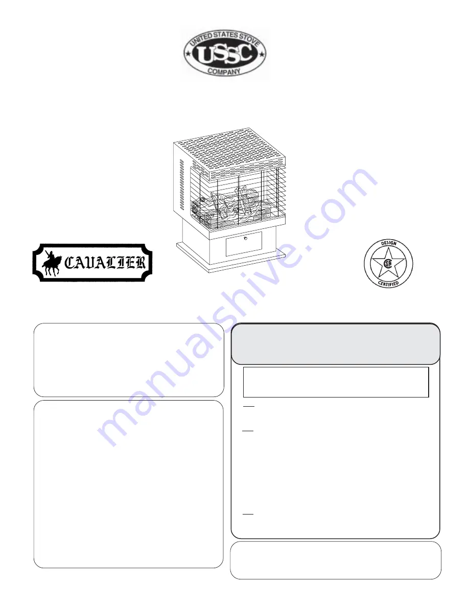
Propane (LPG) Model

C9830L

Natural Gas Model

C9830N

851257A    11/97

WARNINGS

WARNING: If the information in this manual is not followed
exactly, a fire or explosion may result causing property
damage, personal injury or loss of life.

THIS APPLIANCE MAY BE INSTALLED IN
AN AFTERMARKET* MANUFACTURED
(MOBILE) HOME, WHERE NOT
PROHIBITED BY STATE OR LOCAL
CODES.

*Aftermarket:  Completion of sale, not

for purpose of resale, from the
manufacturer.

THIS APPLIANCE IS ONLY FOR USE WITH
THE TYPE OF GAS INDICATED ON THE
RATING PLATE.  THIS APPLIANCE IS NOT
CONVERTIBLE FOR USE WITH OTHER
GASES.

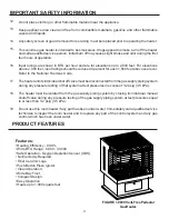
This is an unvented gas-fired heater.  It uses
air (oxygen) from the room in which it is installed.
Provisions for adequate combustion and
ventilation air must be provided.  Refer to
"Adequate Combustion And Ventilation Air"
on page 6 of this manual.

WARNING: Do not use a blower insert, heat
exchanger insert or other accessory not approved
for use with this heater.

VENT-FREE PEDESTAL GAS HEATER

 INSTALLATION AND OPERATION INSTRUCTIONS

Do not store or use gasoline or other flammable vapors
and liquids in the vicinity of this or any other appliance.

WHAT TO DO IF YOU SMELL GAS

• Do not try to light any appliance.
• Do not touch any electrical switch; do not use any phone
in your building.
• Immediately call your gas supplier from a neighbor's
phone. Follow the gas supplier's instructions.
• If you cannot reach your gas supplier, call the fire
department.

Installation and service must be performed by a qualified
installer, service agency or the gas supplier.

Summary of Contents for CAVALIER C9830L

Page 1: ...heater It uses air oxygen fromtheroominwhichitisinstalled Provisions for adequate combustion and ventilation air must be provided Refer to Adequate Combustion And Ventilation Air on page 6 of this manual WARNING Do not use a blower insert heat exchanger insert or other accessory not approved for use with this heater VENT FREE PEDESTAL GAS HEATER INSTALLATION AND OPERATION INSTRUCTIONS Do not store...

Page 2: ... 15 16 PARTS LIST FOR BURNER LOG ASSEMBLY 17 18 TROUBLE SHOOTING 19 20 OPTIONAL EQUIPMENT 21 NOTE 22 LIMITED WARRANTY POLICY 23 NOTICE Installation and repair must be done by a qualified service person The appliance should be inspected before use and at least annually by a professional service person More frequent cleaning may be required due to excessive lint from carpeting bedding material etc I...

Page 3: ... performed by a qualified installer service agency or the gas supplier To prevent malfunction and or sooting an unvented gas heater should be cleaned at least annually byaprofessionalserviceperson Morefrequentcleaningmayberequiredduetoexcessivelintfrom carpeting etc It is imperative that control compartments burners and circulating air passageways be kept clean Correct placement of the ceramic fib...

Page 4: ...nditsindividualshutoffvalvemustbedisconnectedfromthegassupplypipingsystem during any pressure testing of that system at test pressures in excess of 1 2 psig 3 5 kPa The heater must be isolated from the gas supply piping system by closing its individual manual shutoff valve during any pressure testing of the gas supply piping system at test pressures equal to or less than 1 2 psig 3 5 kPa Do not us...

Page 5: ...ve position to light maintain a standing pilot 4 ON Gasflowtocompletesystem frontburnerignition FrontBurnerControlKnob Infinitecontrol rotateclockwisetominimumrateandcounter clockwiseformaximumrate RearBurnerControlKnob Has3positions 1 OFF Gastorearburnerisshutoffatcontrol 2 ON MAX Maximumgasflowtorearburner 3 MIN Minimumgasflowratetorearburner 5 GLOVES ARE RECOMMENDED WHEN HANDLING CERAMIC FIBER ...

Page 6: ... 6 x 10 kg per pa sec m or less with openings gasketed or sealed and b Weather stripping has been added on openable windows and doors and c Caulking or sealants are applied to areas such as joints around window and door frames between soleplates and floors between wall ceiling joints between wall panels at penetrations for plumbing electrical and gas lines and at other openings The National Fuel G...

Page 7: ...d when facing the front of the heater FIGURE3 MinimumClearances Maintain these clearances to ensure adequate space around air opening for proper operation Minimum clearances to combustibles Topofheater 36 Sidesofheater 8 Front of heater 42 Rearofheater 4 L2 12 L1 15 1 2 W 12 H 8 36 8 8 4 42 If the area in which the heater may be operated is smaller than that defined as an unconfined space or if th...

Page 8: ... local codes Only use pipe of 1 2 or greater diameter to allow full gas volume to heater Excessive pressure loss will occur if the pipe is too small A manual shutoff valve union and plugged 1 8 NPT pressure tapping point must be installed upstream of the heater FIGURE 4 A sediment trap must be installed upstream of the heater to prevent moisture and contaminants from passing through the pipe to th...

Page 9: ...pering IfthepressureisnotasspecifiedinProduct Specifications Page5 contactyourdealerandreplacetheregulator FIGURE6 PressureTestPointLocation Control Valve Control Bracket Rightside view facing heater Test Pressure Input Test Pressure Output Gas Inlet Connection 3 8 NPT FIGURE5 RearViewof9830Vent FreeGasHeater The gasinletconnectionis3 8 NPT madeat therearofthemaincontrolthroughtheareaat therearoft...

Page 10: ...iberlogs Donothandletheselogswithyourbarehands Always wearglovestopreventskinirritationfromceramicfibers Afterhandlinglogs washyourhandsgentlywithsoap andwatertoremoveanytracesoffibers PROPER INSTALLATION SEQUENCE 1 Installtherearlog 2 ontherearsetoflocators Visuallychecktoverifythelogissecurelyplacedonthelocators 2 Installthefrontlog 1 onthefrontlocators Visuallychecktoverifythelogissecurelyplace...

Page 11: ...structionsexactly BEFORELIGHTINGsmellallaroundtheapplianceareaforgas Besuretosmellnexttothefloorbecause somegasisheavierthanairandwillsettleonthefloor WHAT TO DO IF YOU SMELL GAS Donotattempttolightanyappliance Donottouchanyelectricswitch donotuseanyphoneinyourbuilding Immediatelycallyourgassupplierfromaneighbor sphone Followthegassupplier sinstructions Ifyoucannotreachyourgassupplier callthefired...

Page 12: ...al tries turn the gas control knob 1 to OFF and call your service technician or your gas supplier 7 Turn gas control knob1 counter clockwise to ON 8 Set the front burner knob 2 to the desired setting rotating counter clockwise to MAX and clockwise to MIN 9 Set the rear burner knob 3 to the desired setting rotating counter clockwise to MAX ON or MIN 10 Closeaccessdoorandturnonelectricalpower 1 STOP...

Page 13: ...ING INSTRUCTIONS Ifthepilotwillnotlightusingthepiezoignitor youcanlightthepilotwithamatch First locatethepilot Thepilot islocatedbetweenthetwoburnertubesontherightend facingtheunit insidethefirebox Tolightpilotwitha match movethegascontrol knob1 pg 12 tothepilotpositionandholddown Lightmatchandplacenearpilot Oncepilotislit continuetoholdtheknobforabouttenseconds Thenfollowsteps7thru10onpage12 PILO...

Page 14: ...on Inspect and clean burner air intake holes Inspect and clean all burner ports Inspect ODS pilot for operation and accumulation of lint at air intake holes Verify flame pattern and log placement for proper operation FLAME APPEARANCE Verify smooth and responsive ignition of main burner and rear burner In normal operation at full rate after 15 minutes the following flame appearance should be observ...

Page 15: ...15 HEATER ASSEMBLY REPLACEMENT PARTS 1 2 3 4 5 6 7 8 11 10 9 12 13 ...

Page 16: ...P 1 4 24538 INSIDE BACK 1 5 69066 FIREBOX WELDMENT 1 6 24534 FIREBOX BOTTOM 1 7 69067 PEDESTAL WELDMENT 1 8 24530 PEDESTAL BASE 1 9 24457 CONTROL DOOR 1 10 89336 BRASS KNOB 1 11 83115 10 32 x 1 2 MACHINE SCREW 1 12 89850 FRONT SCREEN 1 13 89851 BRASS TRIM 2 N S 89824 MAGNETIC LATCH 1 N S 83343 10 x 1 2 HX HD SCREWS 53 N S NOT SHOWN ...

Page 17: ...17 BURNER LOG ASSEMBLY 5 16 15 6 8 9 2 3 7 4 10 11 17 1 19 18 A B C D 20 13 14 12 ...

Page 18: ...ON SLEEVE 1 11 24612 PILOT BRACKET 1 12 89872 O P AMERICA NAT PILOT 1 89873 O P AMERICA L P PILOT 1 N S 83437 10 3 4 HX HD SCREW TO MOUNT PILOT 2 13 89841 3 16 COMPRESSION NUT 1 14 89842 3 16 COMPRESSION SLEEVE 1 15 89853 50 NATURAL BURNER ORIFICE FRONT 1 89854 56 L P BURNER ORIFICE FRONT 1 16 89853 50 NATURAL BURNER ORIFICE REAR 1 89854 56 L P BURNER ORIFICE REAR 1 17 24613 BURNER PAINTED 2 18 89...

Page 19: ...ged Open window and or door ventilation Contact local gas company Clean ODS Pilot Appliance shuts off in use Gas leak Control valve defective Locate and correct all leaks Replace control valve Gas odor even when control knob is in OFF position Gas supply turned off or manual shutoff valve closed Control knob not in PILOT position Control knob not pressed in while in Pilot position Air in gas lines...

Page 20: ...y or partially clogged burner orifice LP regulator shut down due to inlet pressure too high Hand tighten until snug then tighten 1 4 turn more Contact local gas company Replace thermocouple Replace control valve Clean burner or replace burner orifice Replace burner orifice Contact qualified service person Contact local gas company Clean burner or replace burner orifice Clean burner or replace burn...

Page 21: ...T THIS OPTIONAL F40 BLOWER KIT IS AVAILABLE WHERE YOU PURCHASED THIS HEATER OR YOU CAN ORDER DIRECT FROM THE FACTORY BY CONTACTING THE PARTS DEPARTMENT AT THE NUMBER AND ADDRESS ON THE BACK PAGE OF THIS MANUAL BACK VIEW OF 9740 ...

Page 22: ...22 NOTES ...

Page 23: ...ter MUST BE INSTALLED BY A QUALIFIED INSTALLER in accordance with the instructions furnished with the unit The defective heater should be returned at your expense to the dealer from whom the product was purchased or an authorized service agent Any products presented for warranty repair must be accompanied by a dated proof of purchase Since some states do not allow the exclusion on limitation of in...

Page 24: ...UR RECORDS 1 The PART NUMBER 2 The PART DESCRIPTION 3 The MODEL NUMBER 9830N 9830L 4 The SERIAL NUMBER THIS MANUAL WILL HELP YOU TO OBTAIN EFFICIENT DEPENDABLE SERVICE FROM THE FURNACE AND ENABLE YOU TO ORDER REPAIR PARTS CORRECTLY KEEP IN A SAFE PLACE FOR FUTURE REFERENCE WHEN WRITING ALWAYS GIVE THE FULL MODEL NUMBER WHICH IS ON THE NAMEPLATE ATTACHED INSIDE THE FRONT OF THE HEATER WHEN ORDERING...

Reviews: