background image

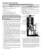
ASSEMBLY INSTRUCTIONS

TOOLS AND MATERIALS REQUIRED FOR INSTALLATION

TOOLS

• 

Pencil

•  6 foot Folding Ruler or Measuring Tape
•  Tin Snips
•  Drill: Hand or Electric
•  1/8” dia. Drill Bit (for sheet metal screws)
•  Screwdrivers (Blade and Phillips type)
•  14mm Nut Driver or Ratchet with 14mm Socket

CAUTION: THIS APPLIANCE IS HEAVY. MAKE 

SURE THAT YOU HAVE ADEQUATE HELP AND USE 

PROPER LIFTING TECHNIQUES WHENEVER MOV-

ING THIS APPLIANCE.

1.  Clean  the  fireplace  opening  properly  disposing  of 

any ashes in a closed metal container. See Safety 

Instructions.

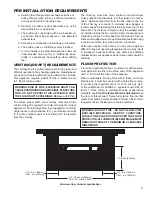
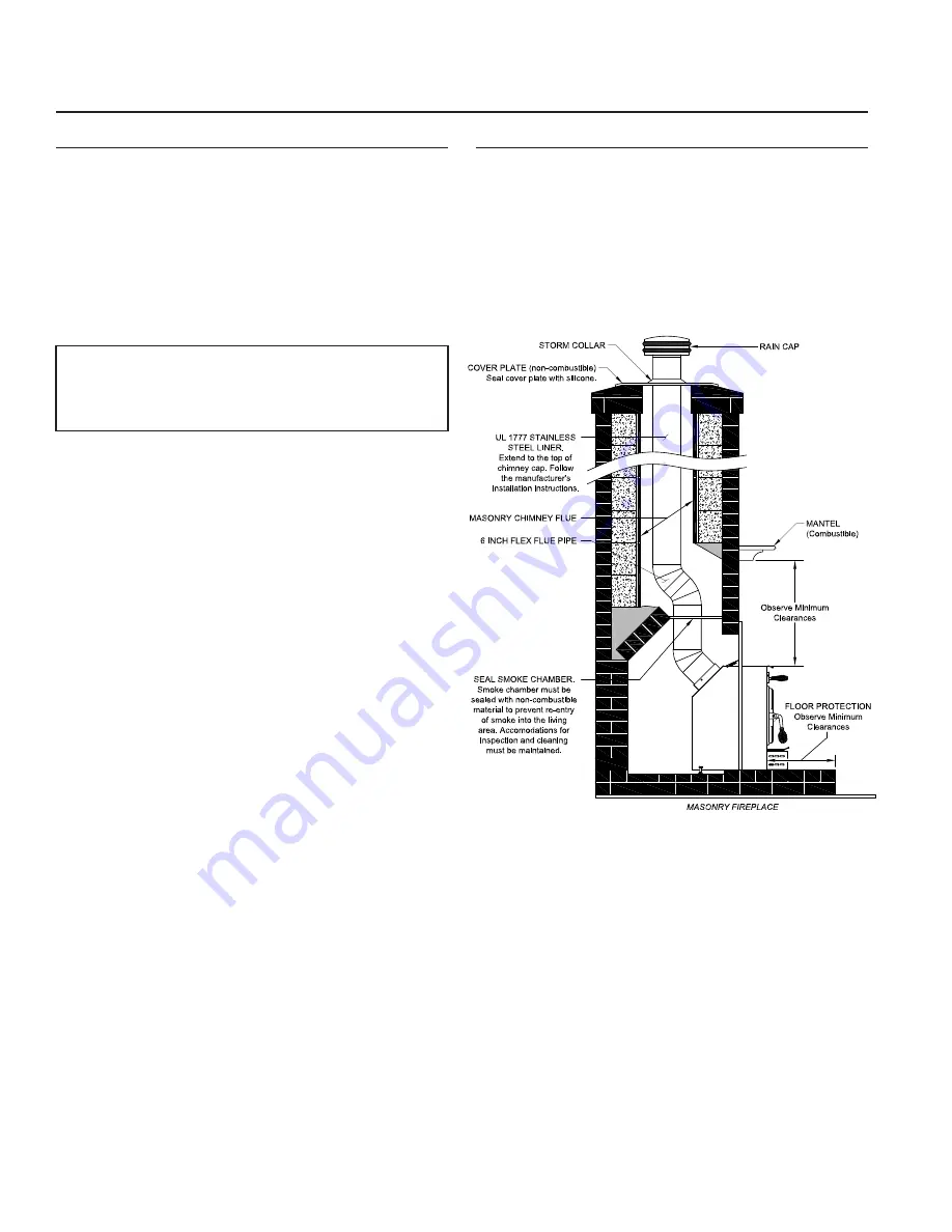
2.  Install a 6˝ (152mm) minimum diameter, continuous 

stainless steel chimney liner into the existing chim-

ney. The liner must extend to the top of the existing 

chimney. Use only listed chimney liners that meet 

UL1777 standards. Follow liner manufacturer instal-

lation instructions.

3.  Remove  or  lock  the  fireplace  damper  in  the  open 

position. Note: Masonry or damper plate may be re-

moved to accommodate the chimney liner provided 

this does not weaken any structural components of 

the existing fireplace or chimney nor reduces protec

-

tion  of  combustible  materials  required  by  national 

building codes. Consult with your local building or fire 

authority before doing this.

4.  Uncrate the appliance, remove all packing materials, 

and any items stored in the firebox.

5.  WARNING:  Any  fireplace  which  has  had  parts  re

-

moved  or  modified  to  accommodate  the  installation 

of this appliance MUST have a warning plate perma-

nently installed in a visible location stating that the 

fireplace is unfit for use with solid fuel. Permanently 

attach the warning plate to a visible location in the 

fireplace.

6.  Position the appliance into the fireplace opening until 

the top lip of the air jacket is flush with the fireplace 

facing.

8.  Level the appliance with the adjusting screws at the 

rear of the appliance.

9.  Connect the chimney liner to the appliance using a 

stainless steel adapter and securing with a minimum 

of three (3) sheet metal screws. The liner MUST be 

attached with the male (or crimped) end of the adapt-

er inside the flue collar of the appliance to allow con

-

densation and/or creosote to drain back into the fire

-

box.

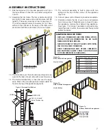
10. Assemble the Surround. Lay pieces face down on 

carpet  or  other  soft  surface  to  protect  finish  during 

assembly. The Surround consists of two side panels, 

a top panel, and a decorative trim frame.

MATERIALS

(NOTE: The following items are NOT included with your stove.)

Flooring Protection: as specified herein.

Chimney Liner: Continuous stainless steel chimney liner 

(as required)

Stainless Steel Adapter (connects the liner to the flue collar)

1/2” Sheet Metal Screws
Furnace Cement (manufacturer recommends Rutland 

Code 78 or equivalent)

Summary of Contents for Country Hearth 2200IE

Page 1: ...E REFERENCE 852497 4805E MODEL 2200IE Fireplace Insert Masonry Fireplace Insert or Zero Clearance metal Fireplace Insert French version is available for download from the United States Stove Company w...

Page 2: ...sary 13 In the event of a chimney fire turn the air controls to the closed position leave the building and CALL THE FIRE DEPART MENT IMMEDIATELY 14 To prevent injury do not allow anyone to use this ap...

Page 3: ...3 2200IE DIMENSIONS 26 11 32 669 0 mm 13 5 32 334 5 mm 27 1 32 686 6 mm 21 13 16 554 0 mm 22 1 4 565 0 mm 15 1 2 394 0 mm 4 11 16 118 8 mm 44 7 32 1123 0 mm 6 00 INSIDE...

Page 4: ...for replacement if the appliance is ever removed The removal of any parts that render the fireplace unusable for burning solid fuel requires a permanent label to be affixed by the in staller that sta...

Page 5: ...chimney is required A stainless steel adapter is recommended for fastening the stainless steel liner to the flue collar The male or crimped end of the adapter must be installed inside the flue collar...

Page 6: ...l packing materials and any items stored in the firebox 5 WARNING Any fireplace which has had parts re moved or modified to accommodate the installation of this appliance MUST have a warning plate per...

Page 7: ...rick extends the life of your stove and radiates heat more evenly If firebricks were removed to posi tion appliance replace them before firing appliance See figure 7 for proper orientation and positio...

Page 8: ...for assistance in solving the problem IMPORTANT INSTALLATION POINTS 1 Size chimney flue to appliance collar This stove requires a minimum 6 diameter flue 2 Never connect this unit to a chimney servin...

Page 9: ...er to make the best possible choice It is EXTREMELY IMPORTANT that you use DRY WOOD only in your wood stove The wood should have dried for 9 to 15 months such that the humidity content in weight is re...

Page 10: ...wood is soaked or freshly cut green Do not use this wood in your stove Large amounts of creosote could be deposited in your chimney creating potential conditions for a chimney fire This appliance is...

Page 11: ...TO MEDIUM BURNS TO FULLY CURE FOR DURABILITY AND A LIFETIME OF SERVICE Proper curing of the high temp paint requires a series of three initial burns The appliance should be allowed to cool off be twee...

Page 12: ...nd establish a good coal bed be fore adjusting to a low burn rate this may take 30 minutes or more depending on your wood Use smaller pieces of wood during start up and a high burn rate to increase th...

Page 13: ...inlet control wide open for 15 20 minutes every time you apply fresh wood This allows wood to achieve the charcoal stage faster and burns wood vapors which might otherwise be depos ited within the hea...

Page 14: ...ances which can ignite explosively in the unit Even small explosions in confined areas can blow out the glass Gasket and Glass cleaning products are available at local retail home centers Manufacturer...

Page 15: ...Tube 1 Secondary Comb 2 15 86670 Tube 2 Secondary Comb 1 Key Part No Description Qty 16 891990 Retainer Tube 3 17 88158 Fiber Board Front 1 18 88159 Fiber Board Rear 1 19 88160 Fiber Blanket 1 20 8059...

Page 16: ...equired thickness T in inches R 1 k x T c C factor is given R 1 C 2 Determine the R value of proposed alternate floor protector a Use formulas in step 1 above to calculate R value of proposed material...

Page 17: ...17 NOTES...

Page 18: ...ULL MODEL NUMBER WHICH IS ON THE NAMEPLATE ATTACHED TO THE HEATER WHEN ORDERING REPAIR PARTS ALWAYS GIVE THE FOLLOWING INFORMATION AS SHOWN IN THIS LIST 1 THE PART NUMBER 2 THE PART DESCRIPTION 3 THE...

Page 19: ...ase qAlternative Heat qMain Heat Source qDecoration qCost qOther _________________________ What was the determining factor for purchasing your new appliance _______ I have read the owner s manual that...

Page 20: ...CUT HERE CUT HERE Fold Here Fold Here United States Stove Company P O Box 151 South Pittsburg TN 37380 USA Fold Here PLACE STAMP HERE...

Reviews: