12
OPERATING INSTRUCTIONS
LIGHTING INSTRUCTIONS
1.
Open access door.
2.
Set front burner to Min. and turn off the rear burner by depressing knob and rotating clockwise
until stop.
3.
Unplug all electric power (optional blower) if service is to be performed.
4.
Push in gas control knob slightly and turn clockwise to "OFF". Do not force.
5.
Close access door.
TURN OFF GAS TO APPLIANCE
6.
Push in the control (knob 1) all the way and
rotate counterclockwise to "PILOT".
The piezo ignitor will light the pilot as the knob
passes "IGN" traveling to the "PILOT". Con
tinue to hold the control (knob 1) in for about
ten (10) seconds after the pilot is lit. Release
knob and it should pop back up. Pilot should
remain lit. If it goes out, repeat steps 4 through
6. If the control (knob 1) does not pop up when
released, stop and immediately call your ser
vice technician or gas supplier. If the pilot will
not stay lit after several tries, turn the gas
control (knob 1) to "OFF" and call your service
technician or your gas supplier.
7.
Turn gas control (knob1) counterclockwise
to "ON".
8.
Set the front burner (knob 2) to the desired
setting rotating counterclockwise to
MAX. and clockwise to MIN.
9.
Set the rear burner (knob 3) to the desired
setting rotating counterclockwise to
MAX./ ON or MIN.
10. Close access door and turn on electrical power.
1.
STOP! Read the safety information on the
previous page.
2.
Turn off all electrical power and open the
access door.
3.
Turn off the rear burner and set the front burner
to low.
4.
Push in gas control (knob 1) slightly and turn
clockwise to "OFF".
NOTE: Knob cannot be turned from "PILOT" to
"OFF" unless knob is pushed in slightly. Do not
force.
5.
Wait five (5) minutes to clear out any gas. Then
smell for gas, including near the floor. If you
smell gas, STOP! Follow "B" in the safety
information on the previous page. If you don't
smell gas, go on to the next step.
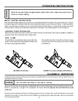
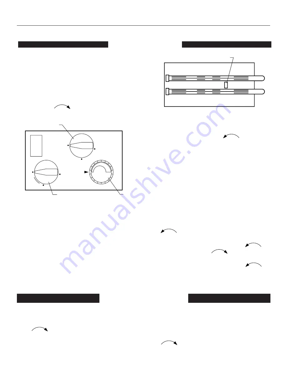
PILOT LOCATION
TOP VIEW OF BURNER ASSEMBLY
OFF
IG
N
PILOT
ON
OFF
ON
MAX
MIN
Meritik
MAXITROL
KNOB 1
1. PILOT
2. FRONT BURNER
3. REAR BURNER
KNOB 2
KNOB 3
Summary of Contents for Fiero C9947L
Page 16: ...HEATER ASSEMBLY 16 ...
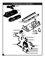
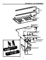
Page 18: ...BURNER AND LOG ASSEMBLY 14 4 2 18 20 19 11 8 9 18 3 5 6 13 16 15 1 12 7 17 10 ...
Page 26: ...NOTES 26 ...
Page 34: ...1 5 HEATER ASSEMBLY REPLACEMENT PARTS 1 2 3 4 5 6 7 8 11 10 9 12 13 ...
Page 36: ...BURNER LOG ASSEMBLY 1 7 5 16 15 6 8 9 2 3 7 4 10 11 17 1 19 18 A B C D 20 13 14 12 ...
Page 41: ...NOTES 2 2 ...


