Annual inspection and cleaning by your dealer or qualified service technician is recommended to prevent
malfunction and/or sooting.
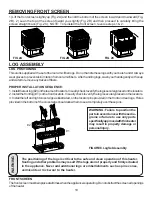
Remove front screen, (see page 6). Carefully lift screen from locating stubs and set aside during cleaning.
Refer to instructions on page 6 for installation of screen. Do not operate the unit with the screen
removed.
Remove logs, handling carefully by holding gently at each end. Gloves are recommended to prevent skin
irritation from ceramic. If the skin becomes irritated, wash gently with soap and water. Refer to manual for
correct log placement.
13
OPERATING INSTRUCTIONS
Wait 30 seconds before readjusting the heater when the control has been turned
down to a lower setting.
WARNING
MATCH LIGHTING INSTRUCTIONS
If the pilot will not light using the piezo ignitor, you can light the pilot with a match. First, locate the pilot. The pilot
is located between the two burner tubes on the right end (facing the unit), inside the firebox. To light pilot with a
match, move the gas control (knob 1, pg. 12) to the pilot position and hold down. Light match and place near pilot.
Once pilot is lit, continue to hold the knob for about ten seconds. Then follow steps 7 thru 10 on page 12.
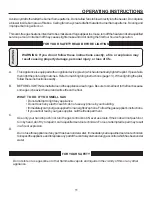
PILOT FLAME
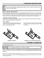
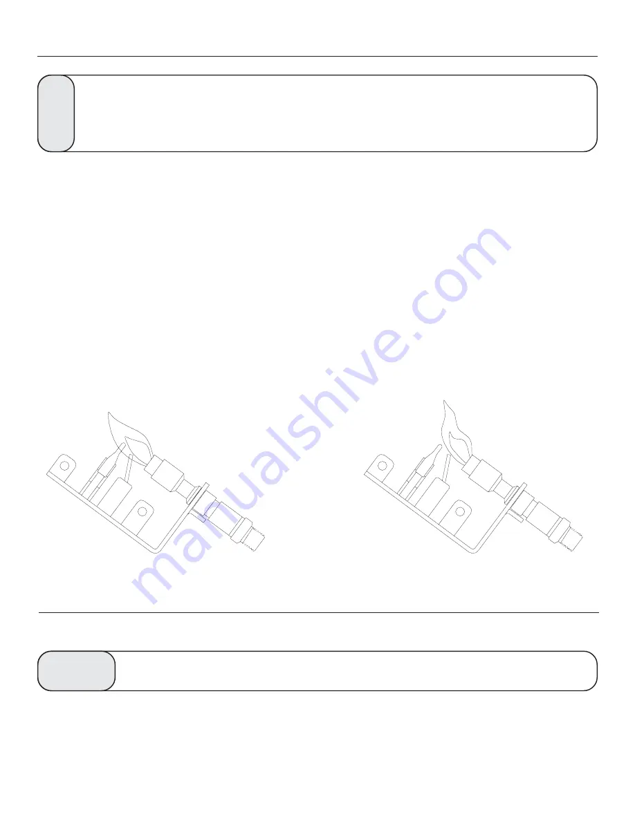
The pilot flame should always be present when the
heater is in operation and should just touch the top of
the thermocouple tip (FIGURE 9).
If the pilot flame does not touch the thermocouple,
then the main burner is unlikely to function reliably
(FIGURE 10).
CHECKING FLAME APPEARANCE
Flames from the pilot, front and rear burner should be visually checked when the heater is installed. In addition a
periodic visual check of the flames should be made.
WARNING
Turn off heater and allow to cool before cleaning.
CLEANING / SERVICING
FIGURE 9. Pilot Flame
FIGURE 10. Incorrect Shape of Pilot Flame
Summary of Contents for Fiero C9947L
Page 16: ...HEATER ASSEMBLY 16 ...
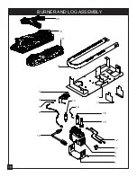
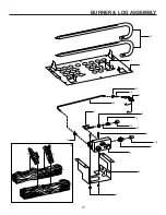
Page 18: ...BURNER AND LOG ASSEMBLY 14 4 2 18 20 19 11 8 9 18 3 5 6 13 16 15 1 12 7 17 10 ...
Page 26: ...NOTES 26 ...
Page 34: ...1 5 HEATER ASSEMBLY REPLACEMENT PARTS 1 2 3 4 5 6 7 8 11 10 9 12 13 ...
Page 36: ...BURNER LOG ASSEMBLY 1 7 5 16 15 6 8 9 2 3 7 4 10 11 17 1 19 18 A B C D 20 13 14 12 ...
Page 41: ...NOTES 2 2 ...

