background image

20

© 2022 United States Stove Company

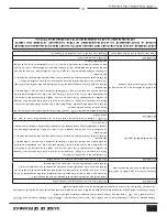
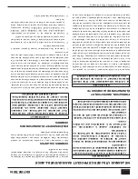
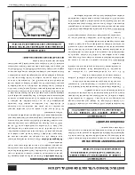
TROUBLESHOOTING GUIDE

ATTENTION: THIS WOOD HEATER NEEDS PERIODIC INSPECTION AND REPAIR FOR PROPER OPERATION. 

IT IS AGAINST FEDERAL REGULATIONS TO OPERATE THIS WOOD HEATER IN A MANNER INCONSISTENT 

WITH OPERATING INSTRUCTIONS IN THIS MANUAL.

•  Disconnect the power cord before performing any maintenance! NOTE: Turning the ON/OFF Switch to ”OFF” does 

not disconnect all power to the electrical components of the stove.

•  Never try to repair or replace any part of the stove unless instructions for doing so are given in this manual. All other 

work should be done by a trained technician.

PROBLEM

CAUSE: To rich air/fuel mixture

Orange, lazy flame 

excessive fuel build-

up in the burnpot

Clean out the burnpot and burnpot housing

Make sure that the viewing door is closed and sealed properly. If not, adjust door catch and/

or replace door gaskets.

Check that all outside connections are clear of any obstructions.

Check the exhaust system; clean as needed.

PROBLEM

CAUSE: Burnpot burns out of fuel

Fire goes out or stove 

shuts down.

Hopper is empty, refill the hopper.

Loss of draft pressure. Make sure that the viewing door is closed and sealed properly. If not, 

adjust door catch and/or replace door gaskets. Check that all outside connections are clear 

of any obstructions. Check the exhaust system; clean as needed.

Check that the pressure switch connection to the firebox is free of ash or clear of obstructions.

Auger system is jammed or there is a “bridging” of the fuel in the hopper, preventing fuel 

from flowing into the auger feed system.

PROBLEM

CAUSE: Auto-Start Igniter fails to ignite the fuel in the burn pot.

Stove does not start 

a fire when the “ON” 

button is pushed

Turn the stove “OFF”. Clear the unburned fuel from the burnpot and try again.

Check the pellet quality. Replace if moist, wet, or dirty.

Loss of draft pressure. Make sure that the viewing door is closed and sealed properly. If not, 

adjust door catch and/or replace door gaskets. Check that all outside connections are clear 

of any obstructions. Check the exhaust system; clean as needed.

Check that the auto-start igniter is not blocked with ash or soot. (The igniter is located 

behind the burnpot on the back wall of the firebox.)

Check that the pressure switch connection to the firebox is free of ash or clear of obstructions.

The auto-start igniter gets “red hot” during start-up. If you can not visibly see the igniter 

glowing during start-up, then the igniter may need to be replaced or there is a problem with 

the electrical control system.

PROBLEM

CAUSE: Power outage

Experiencing low 

exhaust pressure

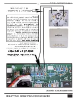
Turn off the circuit board and turn it back on.

Summary of Contents for KING KP5522

Page 1: ...lding or fire officials about permits restrictions and installation requirements in your area NEVER OPERATE THIS PRODUCT WHILE UNATTENDED CAUTION Please read this entire manual before you install or u...

Page 2: ...et fuel this heater has been shown to deliver heat at a rate of 32 591 to 13 640 Btu hr This heater achieved a particulate emissions rate of 1 5 g hr when tested to method ASTM E 2779 EPA Method 28R a...

Page 3: ...and_____________________________________________ If no Date of inspection of existing venting system ________________________________________________________________ COMMISSIONING Confirm Hearth Pad I...

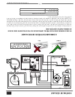
Page 4: ...ires out of the top of the stove There will be two wire harnesses as shown 2 Unpack the top mount controls and ensure that the wiring harness shown is attached securely 3 Connect the factory installed...

Page 5: ...SEVER THE GROUNDING PLUG DO NOT ROUTE THE ELECTRICAL CORD UNDERNEATH IN FRONT OF OR OVER THE HEATER DO NOT ROUTE THE CORD IN FOOT TRAFFIC AREAS OR PINCH THE CORD UNDER FURNITURE CAUTION BURNING FUEL C...

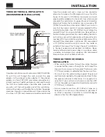
Page 6: ...e of the chimney tee for an interior vertical installation A Floor Protector of 1 26 mm thick is recommended for this installation D B C B A A Rear through wall 1 25 mm B Side 6 152 mm C Front 6 152 m...

Page 7: ...rate paint or protective coating to ensure grounding Vent must be 3 or 4 inch PL Vent and must extend a minimum or 36 914 mm above the roof line of the mobile home and must be installed using a certif...

Page 8: ...pellet vent pipe is not furnished with the unit and must be purchased separately PELLET VENT INSTALLATION The installation must include a clean out tee to enable collection of fly ash and to permit pe...

Page 9: ...nd void your warranty HORIZONTAL EXHAUST VENT INSTALLATION 1 Locate your pellet stove in a location which meets the requirements of this manual but in an area where it does not interfere with the hous...

Page 10: ...o get above the snowdrift line This same installation can be used if your heater is below ground level by simply adding the clean out section and vertical pipe inside until ground level is reached Wit...

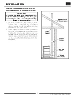
Page 11: ...s A 6 venting system You must have the existing chimney system cleaned and or inspected by a qualified chimney sweep before proceeding with the installation of your pellet stove 2 To the right is an e...

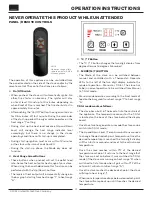
Page 12: ...t range 5 C C F Button The C F button changes the two digit display from degrees Celsius to degrees Fahrenheit D MODE M T BUTTON The Mode of the stove can be switched between manual and controlled wit...

Page 13: ...heater is in the manual mode the optional thermostat will not properly control the unit When adjusting the Draft Fan setting try only 1 setting above or below the heat setting It is better to leave t...

Page 14: ...the stove cycle between the preselected desired heat range setting 1 to 5 and the minimum heat range setting of 1 The T Stat will not turn the stove on and off When the desired room temperature has be...

Page 15: ...reduced performance Store your pellets in a dry place DO NOT store the fuel within the installation clearances of the unit or within the space required for refuelling and ash removal Doing so could re...

Page 16: ...tove will have to fully shut down and turn off before you will be able to restart the stove IGNITOR 1 Fill hopper and clean burn pot 2 Press the On Off button Make sure the green light comes on 3 Adju...

Page 17: ...rswitch shuttingthefuelfeedoff Thestove will shut down and show E2 on the two digit display The stove has to fully shut down before restarting INTERIOR CHAMBERS Burn Pot Periodically remove and clean...

Page 18: ...rush specifically designed for the type of chimney in use A qualified chimney sweep can perform this service It is also recommended that before each heating season the entire system be professionally...

Page 19: ...gloves carefully remove any loose pieces of glass from the door frame 4 Replace the glass and gasket making sure the gasket runs the full perimeter of the glass edge 5 Re install the retainer and eigh...

Page 20: ...d or replace door gaskets Check that all outside connections are clear of any obstructions Check the exhaust system clean as needed Checkthatthepressureswitchconnectiontothefireboxisfreeofashorclearof...

Page 21: ...he stove is in the Shut Down state waiting for the off button or for a 15 minute period after the stove was turned off or for the stove to cool down or for the door to be closed Flashing dash in Heat...

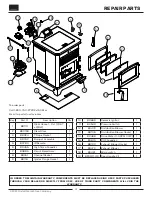
Page 22: ...ass 1 3 88324 1 Rope Gasket 1 4 69762 Burnpot Assembly 1 5 80780 IR Remote 1 6 80455 High Temp Snapdisc 1 7 80886 Circuit Board Assy 1 8 88351 Channel Gasket 1 9 88118 Ignitor Flange Gasket 1 10 80869...

Page 23: ...s are ordered Before contacting customer service write down the model number and the serial number of this unit That information can be found on the certification label attached to the back of the uni...

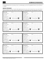
Page 24: ..._____ Engineer Name _____________________________________ License No _________________________________________ Company ___________________________________________ Telephone No ________________________...

Page 25: ...2022 United States Stove Company 25 NOTES...

Page 26: ...de rechange les informations contenues dans ce manuel vous aideront vous assurer que les bons articles sont command s Avant de contacter le service client notez le num ro de mod le et le num ro de s r...

Page 27: ...1 4 69762 Assemblage Burnpot 1 5 80780 Ir distance 1 6 80455 Snapdisc temp rature lev e 1 7 80886 Assy de carte de circuit imprim 1 8 88351 Joint de canal 1 9 88118 Joint de bride d igniteur 1 10 8086...

Page 28: ...nt deux fois par seconde Cela indique que le po le fonctionne normalement et qu une condition de temp rature excessive existe provoquant l arr t du combustible Indicateur de r glage du niveau de chale...

Page 29: ...st me vis sans fin est bloqu ou il y a une vo te de combustible dans la tr mie qui emp che le combustible de s couler dans le syst me d approvisionnement vis sans fin PROBL ME CAUSE L allumeur automat...

Page 30: ...rait 1 Une fois le radiateur refroidi retirez la porte du radiateur 2 Retirez le joint de corde de la porte puis les crous retenant le dispositif de retenue du verre en place 3 Tout en portant des gan...

Page 31: ...p cialement con ue pour le type de chemin e utilis Un ramoneur qualifi peut fournir ce service Il est galement conseill d inspecter de nettoyer et si n cessaire de r parer la totalit du syst me avant...

Page 32: ...int et la mention E2 s affiche sur l cran deux chiffres Le po le doit s arr ter compl tement avant de pouvoir tre red marr CHAMBRES INT RIEURES Pot de combustion Retirez et nettoyez p riodiquement le...

Page 33: ...le voyant vert s allume 3 Ajustez la vitesse d alimentation au r glage souhait en appuyant sur le bouton Avance du niveau de chaleur Si le feu ne d marre pas dans 12 minutes appuyez sur Marche Arr t...

Page 34: ...inf rieur 300 parties par million Les granul s mous contenant une quantit excessive de sciure de bois en vrac qui ont t ou sont mouill s r duiront les performances Rangez vos pellets dans un endroit...

Page 35: ...entre le r glage pr s lectionn de la plage de chaleur d sir e 1 5 et le r glage de la plage de chaleur minimale de 1 Le T Stat n allumera ni ne teindra le po le Lorsque la temp rature ambiante souhai...

Page 36: ...uand le syst me de chauffage est en mode manuel le thermostat en option ne contr lera pas correctement l unit Lorsque vous ajustez le r glage du ventilateur de tirage essayez seulement 1 r glage au de...

Page 37: ...heat output will incrementally change on the bar graph starting from heat range 1 to heat range 5 C C F Button The C F button changes the two digit display from degrees Celsius to degrees Fahrenheit D...

Page 38: ...rs un tuyau de connecteur de 6 pouces les illustrations ci dessous ne sont que des exemples Veuillez confirmer tous les codes du b timent locaux ou ragulations ayant comp tence avant de demander un in...

Page 39: ...chutes de neige il est recommand que l installation soit plus grand que 3 pieds 0 91 m pour obtenir au dessus de la ligne de cong re Cette m me installation peut tre utilis e si votre chauffe eau est...

Page 40: ...re garantie ECHAPPEMENT HORIZONTALES INSTALLATION 1 Localisez votre po le granul s dans un endroit qui r pond aux exigences de ce manuel mais dans une zone o il ne g ne pas la charpente de la maison l...

Page 41: ...riodique du syst me d chappement Les coudes 90 degr s accumulent les cendres volantes et la suie r duisant ainsi le d bit d chappement et les performances du po le Chaque coude ou t r duit le potenti...

Page 42: ...aide d un coupe feu de plafond certifi et d un chapeau de pluie Lors du d m nagement de votre maison mobile toute ventilation ext rieure doit tre enlev e pendant le d placement de la maison mobile Apr...

Page 43: ...ment grand pour s tendre sur au moins 6 po 153 mm l avant 6 po 153 mm de chaque c t et 1 po 26 mm derri re le po le La protection du plancher doit s tendre sous et 2 po 51 mm de chaque c t du t de che...

Page 44: ...DE PRISE ET NE COUPEZ PAS LA FICHE DE TERRE N ACHEMINEZ PAS LE CORDON LECTRIQUE SOUS DEVANT OU SUR LE PO LE NE FAITES PAS COURIR LE CORDON LECTRIQUE DANS LES ZONES DE PASSAGE ET NE LE COINCEZ PAS SOUS...

Page 45: ...de c bles comme illustr tape 2 D ballez les meilleurs contr les de montage et de veiller ce que le faisceau de c blage illustr est x tape 3 Connecter les install s en usine faisceaux de c blage sur l...

Page 46: ...n date d inspection du syst me de ventilation existant ___________________________________________________________________ MISE EN SERVICE Confirmer l installation du tapis de foyer conform ment aux i...

Page 47: ...let peut effectuer le taux r el d alimentation en carburant et de br ler fois Taux d alimentation en carburant peut varier par autant que 20 Utiliser PFI carburant list pour de meilleurs r sultats Tem...

Page 48: ...fortune lors de l installation de ce radiateur Contactez les responsables locaux du b timent ou des pompiers pour conna tre les permis les restrictions et les exigences d installation dans votre r gio...

Reviews: