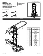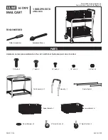

LC-37 Log Cart
U.S. Stove Company
227 Industrial Park Road
South Pittsburg, Tennessee 37380
www.usstove.com Phone: (800)-750-2723
852339C
Thank you for purchasing the LC-37 Log Cart. The following instructions show you how to easily
assemble your new cart.
Tools Required:
1)
19mm socket wrench (or adjustable crescent wrench).
2)
5/
32” hex wrench (supplied).
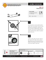
1.
Place
the
B
ase
S
upport
L
egs
bars
(F) on either ends of the
A
xle (I).
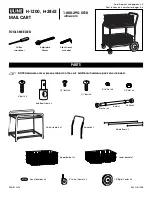
2.
Place the
thicker Washers
(L) on each end of the
A
xle.
3.
Place a
W
heel (J) on each end
of the Axle
followed by the
thinner Washer (
K) and secure the
wheel assemblies by threading a 12mm
H
ex
N
ut (M) on each end of the
A
xle.
4.
Position the
W
ooden handle (H) into the
B
ack
V
ertical
S
upport
Bars
(B).
Secure the
hand
le
with two 5/8”
Machine S
crews (N).
Do not tighten the fasteners
until all parts have been assembled.
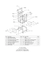
5.
Insert
two 1”
M
achine
S
crews (O) in the two holes at the rear of the
B
ottom
V
ertical
S
upport
B
ars (B). Align screws through the rear set of holes in the
B
ase
S
upport
L
egs (F) and thread
into the
B
ase
S
eparation
B
ar (G).
6.
Insert
the 5/8”
Machine Screws
(N) in the remaining holes to secure the
Back Vertical Support
bars (B) to the
B
ase
Support Legs
(F).
7.
Insert two 1" Machine Screws (O) in the two holes at the front of the F
ront
V
ertical
S
upport
B
ars (D)
. Align screws through the
front set of holes in the
Base Support Legs
(F) and thread
into the
B
ase
S
eparation
B
ar (G).
8.
Secure the Center Back Vertical Support Bar (C) to the Upper Separation Bar (A) by
threading
two 5/8" Machine Screws (N) through the Upper Separation Bar (A)
i
nto the Center
Back Vertical Support Bar (C).
9.
Secure the Center Back Vertical Support Bar (C) to the Base Separation Bar (G) by
threading
a 5/8" Machine Screw (N) through the Base Separation Bar (G) into the Center
Back Vertical Support Bar (C).
10.
Attach the Center Front Vertical Support Bar (E) to the Base Separation Bar (G) by threading
a 5/8" Machine Screw through the Vertical Support Bar (E) into center hole of the Base
Separation Bar (G).
11.
Secure the Front Vertical Support Bars (D and E) to the Upper Separation Bar (A) using 5/8"
Machine Screws.
12.
Securely tighten all screws.
Assembly