background image

-9-

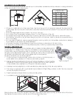
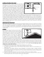
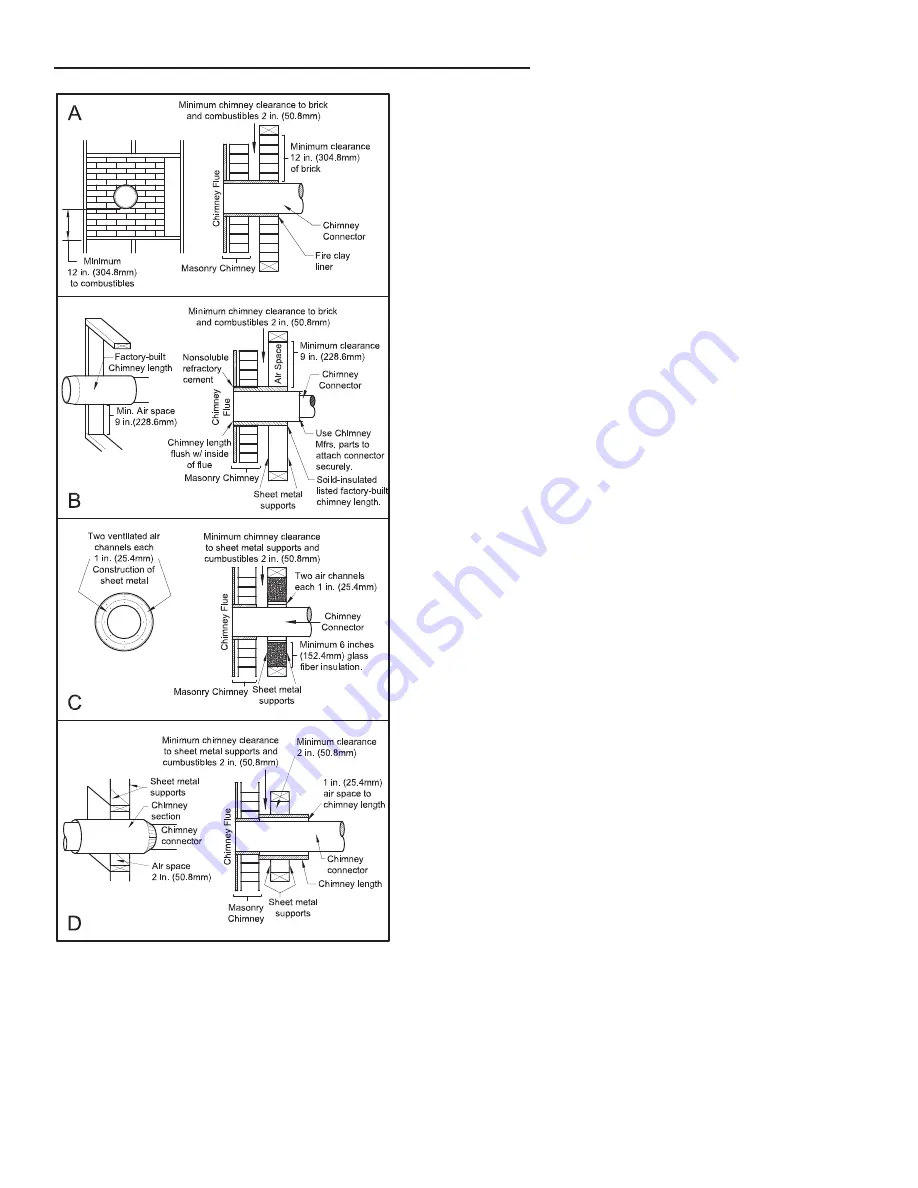
COMBUSTIBLE WALL CHIMNEY CONNECTOR PASS-THROUGHS

METHOD A -

  12”  (304.8  mm)  Clearance  to  Combustible  Wall 

Member: Using a minimum thickness 3.5” (89 mm) brick and a 

5/8”  (15.9  mm)  minimum  wall  thickness  clay  liner,  construct  a 

wall  pass-through.  The  clay  liner  must  conform  to  ASTM  C315 

(Standard  Specification  for  Clay  Fire  Linings)  or  its  equivalent. 

Keep a minimum of 12” (304.8 mm) of brick masonry between 

the  clay  liner  and  wall  combustibles.  The  clay  liner  shall  run 

from the brick masonry outer surface to the inner surface of the 

chimney flue liner but not past the inner surface. Firmly grout or 

cement the clay liner in place to the chimney flue liner.

METHOD B - 

9”  (228.6  mm)  Clearance  to  Combustible  Wall 

Member: Using a 6” (152.4 mm) inside diameter, listed, factory-

built Solid-Pak chimney section with insulation of 1” (25.4 mm) or 

more, build a wall pass-through with a minimum 9” (228.6 mm) 

air space between the outer wall of the chimney length and 

wall combustibles. Use sheet metal supports fastened securely 

to wall surfaces on all sides, to maintain the 9” (228.6 mm) air 

space.  When  fastening  supports  to  chimney  length,  do  not 

penetrate  the  chimney  liner  (the  inside  wall  of  the  Solid-Pak 

chimney). The inner end of the Solid-Pak chimney section shall 

be flush with the inside of the masonry chimney flue, and sealed 

with a non-water soluble refractory cement. Use this cement to 

also seal to the brick masonry penetration.
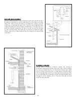
METHOD C - 

6”  (152.4  mm)  Clearance  to  Combustible  Wall 

Member:  Starting  with  a  minimum  24  gage  (.024”  [.61  mm]) 

6”  (152.4  mm)  metal  chimney  connector,  and  a  minimum  24 

gage ventilated wall thimble which has two air channels of 1” 

(25.4 mm) each, construct a wall pass-through. There shall be a 

minimum 6” (152.4 mm) separation area containing fiberglass 

insulation,  from  the  outer  surface  of  the  wall  thimble  to  wall 

combustibles. Support the wall thimble, and cover its opening 

with a 24-gage minimum sheet metal support. Maintain the 6” 

(152.4  mm)  space.  There  should  also  be  a  support  sized  to  fit 

and hold the metal chimney connector. See that the supports 

are  fastened  securely  to  wall  surfaces  on  all  sides.  Make  sure 

fasteners used to secure the metal chimney connector do not 

penetrate chimney flue liner.

METHOD D - 

2”  (50.8  mm)  Clearance  to  Combustible  Wall 

Member:  Start  with  a  solid-pak  listed  factory  built  chimney 

section  at  least  12”  (304  mm)  long,  with  insulation  of  1”  (25.4 

mm) or more, and an inside diameter of 8” (2 inches [51 mm] 

larger than the 6” [152.4 mm] chimney connector). Use this as a 

pass-through for a minimum 24-gauge single wall steel chimney 

connector. Keep solid-pak section concentric with and spaced 

1”  (25.4  mm)  off  the  chimney  connector  by  way  of  sheet 

metal support plates at both ends of chimney section. Cover 

opening with and support chimney section on both sides with 

24 gage minimum sheet metal supports. See that the supports 

are  fastened  securely  to  wall  surfaces  on  all  sides.  Make  sure 

fasteners used to secure chimney flue line do not penetrate the 

inner liner.

NOTES:

1.  Connectors to a masonry chimney, excepting method B, shall extend in one continuous section through the 

wall pass-through system and the chimney wall, to but not past the inner flue liner face.

2. 

A chimney connector shall not pass through an attic or roof space, closet or similar concealed space, or a 

floor, or ceiling.

Summary of Contents for VOGELZANG VG2020

Page 1: ...nstallation Could Void Your Warranty Certified to UL 1482 2011 R2015 and ULC S627 00 R2016 Mobile home approved U S ONLY U S Environmental Protection Agency Certified to comply with 2020 particulate e...

Page 2: ...CONTACT MAY CAUSE SKIN BURNS DO NOT USE CHEMICALS OR FLUIDS TO IGNITE THE FIRE DO NOT LEAVE THE STOVE UNATTENDED WHEN THE DOOR IS SLIGHTLY OPENED DO NOT BURN GARBAGE FLAMMABLE FLUID SUCH AS GASOLINE N...

Page 3: ...to the top of the unit as shown using the 3 5 16 18 x 1 1 2 bolts 3 washers and 3 weld tabs provided in the parts box FIREBRICK CONFIGURATION Replace the Firebrick as shown in the illustration 5 16 1...

Page 4: ...e the most time is spent and in the most spacious room possible Recall that wood stoves produce radiating heat the heat we feel when we are close to a wood stove A wood stove also functions by convect...

Page 5: ...E 12 12 305 305 F 22 22 559 559 D B A C E F E D B A C E F E Slide the hose clamp over the aluminium flex pipe Then slide the flex pipe over the air intake tube of the stove Next tighten the hose clamp...

Page 6: ...MUST BE ATTACHED TO THE STRUCTURE OF THE MOBILE HOME SECURING APPLIANCE S ON A PEDESTAL TO THE FLOOR Use the designated holes to secure the unit to the floor SECURING APPLIANCE S WITH LEGS TO THE FLOO...

Page 7: ...e into the room through appliance and chimney connector joints An uncontrollable burn or excessive temperature indicates an excessive draft CHIMNEY Your wood stove may be hooked up with a 6 factory bu...

Page 8: ...as recommended by the manufacturer The chimney must be the required height above the roof or other obstructions for safety and proper draft operation MASONRY CHIMNEY Ensure that a masonry chimney meet...

Page 9: ...nd a minimum 24 gage ventilated wall thimble which has two air channels of 1 25 4 mm each construct a wall pass through There shall be a minimum 6 152 4 mm separation area containing fiberglass insula...

Page 10: ...rain or snow also accelerates the drying time A good indicator of if the wood is ready to burn is to check the piece ends If cracks are radiating in all directions from the center then the wood shoul...

Page 11: ...ling on it and close the door If the piece ignites within 90 seconds from the time it was placed into the stove your wood is correctly dried If ignition takes longer your wood is damp If your wood his...

Page 12: ...t going up the chimney as lost energy Therefore efficiency calculated using the lower heating value of wood will be higher than the efficiency calculated using the higher heating value In the United S...

Page 13: ...these gases is somewhere between 275 F and 500 F Below these temperatures the build up of creosote is promoted Above 500 F heat is wasted since a too large quantity is lost into the atmosphere TO PREV...

Page 14: ...e sold The glass should be washed only when cold PAINT Only clean your stove with a dry soft cloth that will not harm the paint finish If the paint becomes scratched or damaged it is possible to give...

Page 15: ...nt VG2020 BP 1 9 610960 Pedestal Weldment VG2020 BP 1 10 610925 Ashpan Housing VG2020 BL 1 11 610883 Leg Weldment VG2020 BL 4 12 25826 Hearth Plate 1 13 29216 Ash Pan 1 14 610927 Damper Slide Weld 1 1...

Page 16: ...Description Qty 1 83788 Socket Head Screw 1 2 893062 Roller Sleeve 1 3 893156 Wooden Thru Handle 1 4 893164 Door Handle 1 5 891373 Door Hinge Pad Threaded 2 6 40880 Lg Square Cast Door 1 7 88066 Rope...

Page 17: ...17 Notes...

Page 18: ...18 Notes...

Page 19: ...7 Date _____________________ Engineer Name ________________________________ License No ____________________________________ Company _____________________________________ Telephone No _________________...

Reviews: