10
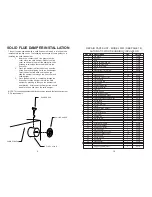
Install the stovepipe as far as possible
into the thimble, but not past the inside
of the flue lining. There should be a
small air space (approximately 1/2 in.)
between the stovepipe and thimble,
allowing for expansion of the stove-
pipe. Seal this airspace with high-tem-
perature caulking or ceramic wool. Fi-
nally, be sure to wire the damper closed
and apply the same sealant you used at
the stovepipe and thimble junction.
Do not vent up through the fireplace
opening, regardless of whether the fire-
place opening is closed.
MASONRY CHIMNEYS have several
positive attributes: If properly built, they
are quite durable, and most
homeowners consider them more at-
tractive perhaps than a non-enclosed
factory built chimney.
And, if the chimney is located within the
confines of the house (that is, not at-
tached to an exterior wall), its mass
alone will store heat longer and con-
tinue to release the heat long after the
fire has died. Masonry chimneys have
many disadvantages though.
Masonry chimneys constructed on an
exterior wall are exposed to cold out-
door temperatures, promoting greater
heater loss, higher accumulations of
creosote, and reduced draft which leads
to poorer heater or furnace perfor-
mance.
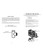
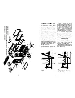
FIREPLACE INSTALLATION
Connection of the stovepipe directly into
the existing masonry chimney over the
fireplace opening is the only approved
method. This installation performs bet-
ter, yielding easy to clean and inspect
for creosote. Before beginning this type
of installation plan carefully; a high de-
gree of skill is required to insure safety.
An entry port for the stovepipe must be
cut through the chimney with minimum
damage to the fire clay liner. Some
involved measurements may be required
to locate the flue liner exactly. Before
cutting, take time to mark the size and
position of the entry port. Position the
entry port so that at least 8 inches of the
flue liner remains below the port.
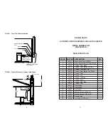
Keep in mind that wood mantels and
combustible trim around the fireplace
must have adequate clearances from
the heater and stovepipe or must be
protected in an approved manner. Also,
be sure to leave at least 24" clearance
between the top of the stovepipe and
the combustible ceiling or other com-
bustibles. Placing the center of the entry
port 2 feet below the ceiling will insure
proper clearance for 6 inch, 8 inch, and
10 inch stovepipes. Next, install a fire
clay (at least 5/8 in. thick) or metal
thimble, being sure that the thimble is
flush with the inner flue lining. Secure
the thimble in place with refractory mor-
tar. The thimble should be surrounded
on all sides with 8 inches of brickwork
(solid masonry units) or 24 inches of
stone.
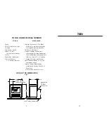
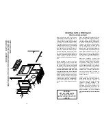
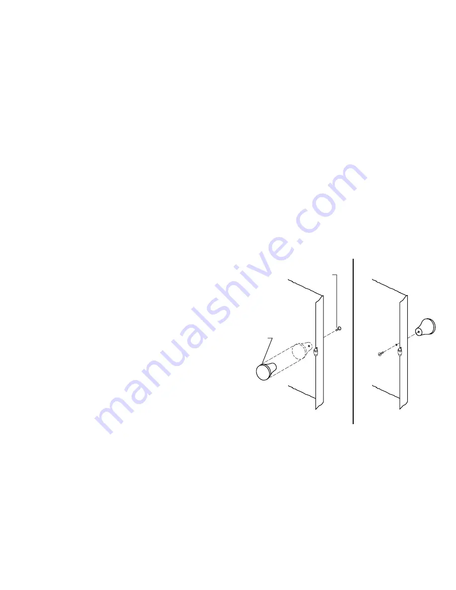
CABINET DOOR KNOB ASSEMBLY
The door knob is mounted inside of the cabinet door to facilitate
shipping and must be reversed for proper usage.
To get cabinet door open, place hand under cabinet frame (right
hand side of cabinet door) and push door out.
INSTALL THE CABINET DOOR KNOB USING THE STEPS
BELOW:
1. Remove the machine screw and door knob (Fig. 9).
2. Place door knob on outside of cabinet door. Then place
machine screw through hole and into door knob and tighten (Fig.
10).
FIG. 9
FIG. 10
CABINET DOOR
KNOB
MACHINE
SCREW
15