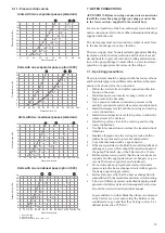
18
15
20
25
30
35
40
45
50
0
5
10
15
20
30XW 1570
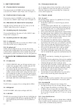
6.9 - Variable flow evaporator
Variable evaporator flow can be used. The controlled flow
rate must be higher than the minimum flow given in the
table of permissible flow rates and must not vary by more
than 10% per minute.
If the flow rate changes more rapidly, the system should
contain a minimum of 6.5 litres of water per kW instead of
3.25 l/kW.
6.10 - System minimum water volume
Whichever the system, the water loop minimum volume is
given by the formula: Volume = Cap (kW) x N litres
Application
N
Normal air conditioning
3.25
Process type cooling
6.5
Where Cap is the nominal system cooling capacity (kW) at
the nominal operating conditions of the installation.
This volume is necessary for stable operation.
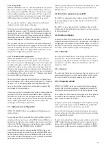
It is often necessary to add a buffer water tank to the circuit
in order to achieve the required volume. The tank must
itself be internally baffled in order to ensure proper mixing
of the liquid (water or brine). Refer to the examples below.
Connection to a buffer tank
Bad
Bad
Good
Good
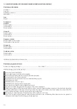
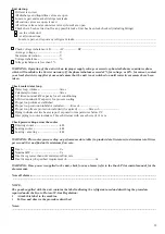
6.8 - Minimum temperature difference
The maximum flow rates recommended by Carrier limit
unit operation with a
∆
T (entering - leaving) of 3 K in the
sections shown below:
Evaporator leaving water temperature, °C
Condenser
lea
ving
w
ater
temper
atur
e,
°C
15
20
25
30
35
40
45
50
55
0
5
10
15
20
30XW 1710
Evaporator leaving water temperature, °C
Condenser
lea
ving
w
ater
temper
atur
e,
°C
Delta_T > 3 K at the condenser
Delta_T > 3 K at the evaporator and the condenser
To achieve a temperature difference of 3 K at the condenser, Carrier recommends the installation
of option 102C.
To achieve a temperature difference of 3 K at the evaporator, Carrier recommends the installation
of option 100C.
30XW-V 1570
30XW-V 1710


