19
Pr
essur
e dr
op
, kP
a
Water flow rate, l/s
Pr
essur
e dr
op
, kP
a
Water flow rate, l/s
Pr
essur
e dr
op
, kP
a
Pr
essur
e dr
op
, kP
a
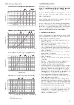
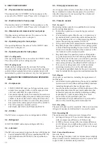
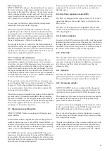
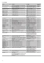
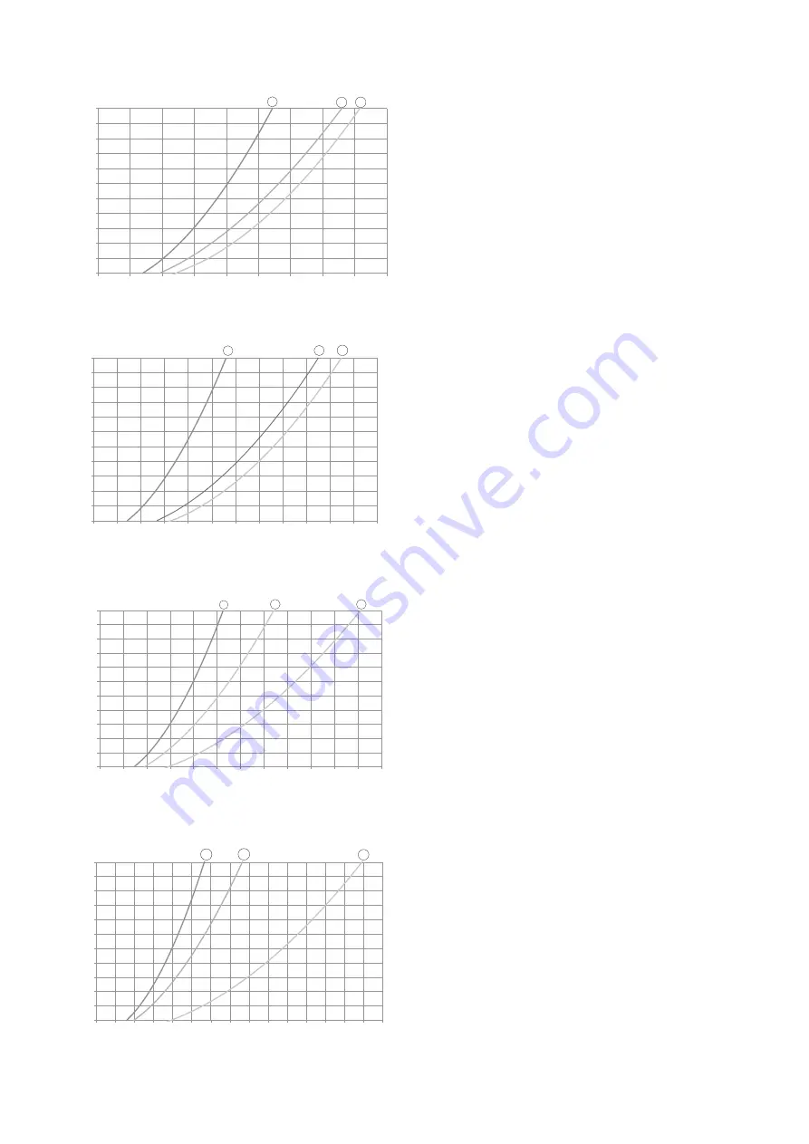
6.11 - Pressure drop curves
Water flow rate, l/s
Water flow rate, l/s
Units with two evaporator passes (standard)
Units with one evaporator pass (option 100C)
Units with two condenser passes (standard)
Units with one condenser pass (option 102C)
10
20
30
40
50
60
70
80
90
100
110
120
0
10
20
30
40
50
60
70
80
90
1
2 3
3
6
9
12
15
18
21
24
27
30
33
36
0
10 20 30 40 50 60 70 80 90 100 110 120
1
2
3
10
20
30
40
50
60
70
80
90
100
110
120
0
10 20 30 40 50 60 70 80 90 100 110 120
1
2
3
3
6
9
12
15
18
21
24
27
30
33
36
0 10 20 30 40 50 60 70 80 90 100 110 120 130 140 150
1
2
3
1 Sizes 580, 630
2 Sizes 810, 880
3 Sizes 1150, 1280, 1470, 1570, 1710
7 - WATER CONNECTIONS
ATTENTION: Before carrying out any water connections
install the water box purge plugs (one plug per water box
in the lower section - supplied in the control box).
For size and position of the heat exchanger water inlet and
outlet connections refer to the certified dimensional drawings
supplied with the unit.
The water pipes must not transmit any radial or axial force
to the heat exchangers nor any vibration.
The water supply must be analysed and appropriate filtering,
treatment, control devices, isolation and bleed valves and
circuits built in, to prevent corrosion, fouling and deteriora-
tion of the pump fittings. Consult either a water treatment
specialist or appropriate literature on the subject.
7.1 - Operating precautions
The water circuit should be designed with the fewest elbows
and horizontal pipe runs at different levels. Below the main
points to be checked for the connection:
•
Follow the water inlet and outlet connection direction
shown on the unit.
•
Install manual or automatic air purge valves at all
high points in the circuit(s).
•
Use a pressure reducer to maintain pressure in the
circuit(s) and install a safety valve and an expansion tank.
•
Install thermometers in both the entering and leaving
water connections.
•
Install drain connections at all low points to allow the
whole circuit to be drained.
•
Install stop valves, close to the entering and leaving
water connections.
•
Use flexible connections to reduce the transmission of
vibrations.
•
Insulate all pipework, after testing for leaks, both to
reduce heat gains and to prevent condensation.
•
Cover the insulation with a vapour barrier.
•
If there are particles in the fluid that could foul the heat
exchanger, a screen filter should be installed ahead of
the pump. The mesh size of the filter must be 1.2 mm.
•
Before system start-up verify that the water circuits are
connected to the appropriate heat exchangers (e.g. no
reversal between evaporator and condenser).
•
Do not introduce any significant static or dynamic
pressure into the heat exchange circuit (with regard to
the design operating pressures).
•
Before start-up verify that the heat exchange fluid is
compatible with the materials and water circuit coating.
•
The use of different metals on hydraulic piping could
generate eletrolytic pairs and consequently corrosion.
It could be needed to add sacrificial anodes.
In case additives or other fluids than those recommend-
ed by Carrier are used, ensure that the fluids are not
considered as a gas, and that they belong to class 2, as
defined in directive 97/23/EC.


