background image

Manufacturer reserves the right to discontinue, or change at any time, specifications or designs without notice and without incurring obligations.

Catalog No. 04-53500160-01

Printed in U.S.A.

Form 50TC-8-16-01SI

Pg 1 

12-17

Replaces: 50TC-8-14-02SI
                 50TC-14SI

Installation Instructions

CONTENTS

Page

SAFETY CONSIDERATIONS

. . . . . . . . . . . . . . . . . . .  1-10

Rated Indoor Airflow (cfm) 

. . . . . . . . . . . . . . . . . . . . . . ..2

Pre-Installation

. . . . . . . . . . . . . . . . . . . . . . . . . . . . . . . . . . . 2

INSTALLATION

 . . . . . . . . . . . . . . . . . . . . . . . . . . . . . .  10-78

Jobsite Survey

. . . . . . . . . . . . . . . . . . . . . . . . . . . . . . . . . . 10

Step 1 — Plan for Unit Location

. . . . . . . . . . . . . . . . . 10

Step 2 — Plan for Sequence of Unit Installation

    11

Step 3 — Inspect Unit

 . . . . . . . . . . . . . . . . . . . . . . . . . . . 11

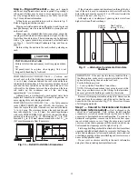
Step 4 — Provide Unit Support

. . . . . . . . . . . . . . . . . . 11

Step 5 — Field Fabricate Ductwork

. . . . . . . . . . . . . . 14

Step 6 — Rig and Place Unit

  . . . . . . . . . . . . . . . . . . . . 15

Step 7 — Convert to Horizontal and Connect

Ductwork

. . . . . . . . . . . . . . . . . . . . . . . . . . . . . . . . . . . . . 15

Step 8 — Install Outside Air Hood

. . . . . . . . . . . . . . . 16

• 50TC 08-14 UNIT SIZES

• 50TC 16 UNIT SIZE

Step 9 — Install External Condensate Trap and

Line

  . . . . . . . . . . . . . . . . . . . . . . . . . . . . . . . . . . . . . . . . . . 19

Step 10 — Make Electrical Connections

. . . . . . . . . 19

• 50TC 08-14 UNIT SIZES

• 50TC 16 UNIT SIZE

Electric Heaters

. . . . . . . . . . . . . . . . . . . . . . . . . . . . . . . . . 29

• 50TC 08-14 UNIT SIZES

• 50TC 16 UNIT SIZE

Humidi-MiZer

®

 System Control Connections

. . . . 32

• 50TC 08-14 UNIT SIZES

• 50TC 16 UNIT SIZE

EconoMi$er

®

 X (Factory-Installed Option) 

 . . . . . . 35

PremierLink™ Controller (Factory Option)

 . . . . . . 49

Supply Air Temperature (SAT) Sensor

 . . . . . . . . . . 53

Economizer Controls 

. . . . . . . . . . . . . . . . . . . . . . . . . . . 58

RTU Open Controller System 

. . . . . . . . . . . . . . . . . . . 63

Field Connections 

. . . . . . . . . . . . . . . . . . . . . . . . . . . . . . 69

Communication Wiring — Protocols

 . . . . . . . . . . . . 71

Local Access

. . . . . . . . . . . . . . . . . . . . . . . . . . . . . . . . . . . . 72

Outdoor Air Enthalpy Control

 . . . . . . . . . . . . . . . . . . . 73

Smoke Detectors

. . . . . . . . . . . . . . . . . . . . . . . . . . . . . . . . 74

Step 11 — Adjust Factory-Installed Options

. . . . . 77

Step 12 — Install Accessories

. . . . . . . . . . . . . . . . . . . 77

Step 13 — Check Belt Tension

 . . . . . . . . . . . . . . . . . . 77

Pre Start-Up and Start-Up

 . . . . . . . . . . . . . . . . . . . . . . . 78

START-UP CHECKLIST

 . . . . . . . . . . . . . . . . .  CL-1, CL-2

SAFETY CONSIDERATIONS

Improper installation, adjustment, alteration, service, main-

tenance, or use can cause explosion, fire, electrical shock or

other conditions which may cause personal injury or property

damage. Consult a qualified installer, service agency, or your

distributor or branch for information or assistance. The quali-

fied installer or agency must use factory-authorized kits or ac-

cessories when modifying this product. Refer to the individual

instructions packaged with the kits or accessories when

installing.

Follow all safety codes. Wear safety glasses and work

gloves. Use quenching cloths for brazing operations and have a

fire extinguisher available. Read these instructions thoroughly

and follow all warnings or cautions attached to the unit. Con-

sult local building codes and appropriate national electrical

codes (in USA, ANSI/NFPA 70, National Electrical Code

(NEC); in Canada, CSA C22.1) for special requirements.

It is important to recognize safety information. This is the

safety-alert symbol 

. When you see this symbol on the unit

and in instructions or manuals, be alert to the potential for per-

sonal injury.

Understand the signal words DANGER, WARNING, CAU-

TION, and NOTE. These words are used with the safety-alert

symbol. DANGER identifies the most serious hazards which

will result in severe personal injury or death. WARNING signi-

fies hazards which could result in personal injury or death.

CAUTION is used to identify unsafe practices, which may re-

sult in minor personal injury or product and property damage.

NOTE is used to highlight suggestions which will result in en-

hanced installation, reliability, or operation.

50TC units for installation in the United States contain use of Carrier's Staged Air Volume (SAV™) 2-speed
indoor fan control system. This complies with the U.S. Department of Energy (DOE) efficiency standard of
2018.
50TC units for installation outside the United States may or may not contain use of the SAV 2-speed indoor
fan control system as they are not required to comply with the U.S. Department of Energy (DOE) efficiency
standard of 2018.
For specific details on operation of the Carrier SAV 2-speed indoor fan system refer to the Variable
Frequency Drive (VFD) Factory-Installed Option 2-Speed Motor Control Installation, Setup, and
Troubleshooting manual.

WARNING

FIRE, EXPLOSION HAZARD

Failure to follow this warning could result in personal

injury or death.
Disconnect gas piping from unit when leak testing at pres-

sure greater than 0.5 psig (3450 Pa). Pressures greater than

0.5 psig (3450 Pa) will cause gas valve damage resulting in

hazardous condition. If gas valve is subjected to pressure

greater than 0.5 psig (3450 Pa), it must be replaced before

use. When pressure testing field-supplied gas piping at

pressures of 0.5 psig (3450 Pa) or less, a unit connected to

such piping must be isolated by closing the manual gas

valve.

WeatherMaker

®

50TC08-16

Single Package Rooftop Cooling Only

 with Puron

®

 (R-410A) Refrigerant

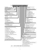
Summary of Contents for Carrier WeatherMaker 50TC A08 Series

Page 1: ...ire extinguisher available Read these instructions thoroughly and follow all warnings or cautions attached to the unit Con sult local building codes and appropriate national electrical codes in USA AN...

Page 2: ...D Failure to follow this warning could cause personal injury death and or equipment damage Puron R 410A refrigerant systems operate at higher pressures than standard R 22 systems Do not use R 22 ser v...

Page 3: ...W7212 EconoMi er IV Non Fault Detection and Diagnostic 1 PremierLink Controller 2 RTU Open Multi Protocol Controller 6 Electro mechanical w 2 Speed Fan and W7220 Economizer Controller Controls Can be...

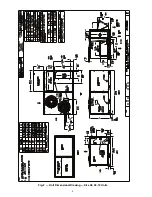
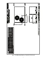
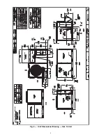
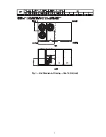
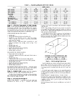
Page 4: ...4 Fig 2 Unit Dimensional Drawing Size 08 09 12 Units...

Page 5: ...5 Fig 2 Unit Dimensional Drawing Size 08 09 12 Units cont...

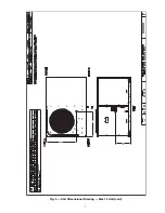
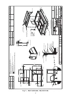
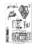
Page 6: ...6 Fig 3 Unit Dimensional Drawing Size 14 Unit...

Page 7: ...7 Fig 3 Unit Dimensional Drawing Size 14 Unit cont...

Page 8: ...8 Fig 4 Unit Dimensional Drawing Size 16 Unit Horizontal Connections Economizer Vertical Connections Economizer...

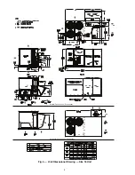
Page 9: ...9 Fig 4 Unit Dimensional Drawing Size 16 Unit cont...

Page 10: ...disposal of frost and ice that will form during the heating defrost mode as well as allow installation of condensate trap per requirements Refer to Step 9 Install Ex ternal Condensate Trap and Line f...

Page 11: ...b details and dimensions are shown in Fig 7 Assemble and install accessory roof curb in accordance with instructions shipped with the curb NOTE The gasketing of the unit to the roof curb is critical f...

Page 12: ...PART WITHOUT THE WRITTEN AUTHORIZATION OF CARRIER CORPORATION 1 DEC 2 DEC 3 DEC ANG MATERIAL AUTHORIZATION NUMBER TITLE 1029120 CURB ASY ROOF ENGINEERING MANUFACTURING ENGINEERING REQUIREMENTS SIZE DR...

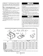
Page 13: ...13 Fig 8 Roof Curb Details Size 16 Unit...

Page 14: ...h UL Underwriters Laboratories code for use with electric heat Before setting the unit onto the curb recheck gasketing on the curb Fig 9 Rigging Details CAUTION PROPERTY DAMAGE HAZARD Failure to follo...

Page 15: ...sion to float if necessary Fig 10 Retrofit Installation Dimensions If the alternative condensate drain location through the bot tom of the unit is used in conjunction with a retrofit curb the hole in...

Page 16: ...t tie wraps secur ing any wiring 4 Carefully lift the hood assembly with metal tray through the filter access opening and assemble per the steps out lined in Economizer Hood and Two Position Damper Ho...

Page 17: ...the steps outlined in Econo mizer Hood and Two Position Hood section Fig 18 Typical Access Panel Locations Fig 19 Economizer Hood Package Location Two Position Damper Hood Removal and Setup factory O...

Page 18: ...damper in place 4 Insert the hood divider between the hood sides See Fig 21 and 22 Secure hood divider with 3 screws on each hood side The hood divider is also used as the bot tom filter rack for the...

Page 19: ...ct switch operation of the conve nience outlet is desired connect the source leads to the load side of the unit disconnect On a unit without a unit mounted disconnect connect the source leads to compr...

Page 20: ...lack pointer the measurement should be 3 75 3 88 in 95 99 mm 7 Tighten the locking screw to secure the shaft to the NFD 8 Turn the handle to the OFF position with red arrow point ing at OFF 9 Install...

Page 21: ...224 3 v BC 231 227 4 v AC 227 226 1 v Maximum deviation is 4 v Determine percent of voltage imbalance Voltage Imbalance 100 x 1 76 This amount of phase imbalance is satisfactory as it is below the max...

Page 22: ...of primary power source is a customer option If local codes permit the transformer primary leads can be connected at the line side terminals on the unit mounted non fused disconnect or HACR breaker s...

Page 23: ...circuit requiring 24 v power use a thermostat cable or equivalent single leads of different colors with minimum of seven leads If the thermostat does not require a 24 v source no C connection require...

Page 24: ...ions provided with this accessory For smaller field disconnects be sure to use 1 2 in screws to mount the disconnect directly to the end panel see Fig 41 In either case set the disconnect verti cal lo...

Page 25: ...mbalance 100 x 1 76 This amount of phase imbalance is satisfactory as it is below the maximum allowable 2 All units except 208 230 v units are factory wired for the voltage shown on the nameplate If t...

Page 26: ...s will provide service power to the unit when the unit disconnect switch is open Other connection methods will result in the convenience outlet circuit being de energized when the unit disconnect swit...

Page 27: ...l cords to exit the cover Check for full closing and latching Fig 47 Weatherproof Cover Installation Factory Option Thru Base Connections This service con nection kit consists of a 1 2 in electrical b...

Page 28: ...at is installed in the 50TC unit the ther mostat must be capable of energizing the G terminal to ener gize the Indoor Fan Contactor whenever there is a space call for heat energizing the W1 terminal T...

Page 29: ...modules that are UL listed for use in a specific size unit Refer to the label on the unit cabinet for the list of approved heaters Unit heaters are marked with Heater Model Numbers But heaters are ord...

Page 30: ...heaters are modular in design One or two heater modules may be used in a unit Heater modules are installed in the compartment below the indoor supply fan outlet Access is through the indoor access pan...

Page 31: ...will have orange pur ple red and brown wires The orange and the purple are the control wires and the red and brown wires feed the safety cir cuit Connect both the orange and the purple wires to the o...

Page 32: ...fer to the installation instructions included with the Carrier Edge Pro Thermidistat device for more infor mation 50TC 16 UNIT SIZE To connect the Carrier humidistat HL38MG029 1 Route the humidistat 2...

Page 33: ...33 Fig 62 Typical Humidi MiZer Adaptive Dehumidification System Humidistat Wiring 50TC 08 14 Unit Sizes...

Page 34: ...34 Fig 63 Typical Humidi MiZer Adaptive Dehumidification System Humidistat Wiring 50TC 16 Unit Sizes HUMIDISTAT...

Page 35: ...e The module is the core of the EconoMi er X system The module is mounted in the unit s control box and includes the user interface for the system The W7220 economizer module provides the basic inputs...

Page 36: ...and AUX1 O All Relay Outputs at 30 Vac Running 1 5A maximum Inrush 7 5A maximum ENVIRONMENTAL Operating Temperature 40 to 150 F 40 to 65 C Exception of display operation down to 4 F 20 C with full re...

Page 37: ...USER INTERFACE The user interface consists of a 2 line LCD display and a 4 button keypad on the front of the econo mizer controller KEYPAD The four navigation buttons see Fig 69 are used to scroll thr...

Page 38: ...TATUS SETPOINTS SYSTEM SETUP ADVANCED SETUP CHECKOUT ALARMS NOTE Some parameters in the menus use the letters MA or MAT indicating a mixed air temperature sensor location before the cooling coil This...

Page 39: ...measured mixed air from MAT sensor Displays _ _ _ F if not connected short or out of range DA TEMP _ _ _ F 0 to 140 F DISCHARGE AIR TEMPERATURE after Heating section Displays when Discharge Air sensor...

Page 40: ...NOT connected VENTMAX With 2 speed fan units VENTMAX L low speed fan and VENTMAX H high speed fan settings are required 2 8 V 2 to 10 Vdc DCV MAXIMUM DAMPER POSITION Displays only if a CO2 sensor is...

Page 41: ...factory defaults when set to YES LCD will briefly flash YES and change to NO but all parameters will change to the fac tory default values NOTE RECHECK AUX2 IN and FANTYPE for required 2 speed values...

Page 42: ...r signals an ERV that the conditions are not good for economizing but are for ERV operation SYS 24 Vac out Issues a system alarm CONNECT EXH1 N A N A Closes the power exhaust fan 2 relay EXH1 ALARMS A...

Page 43: ...2SPEED For damper minimum position settings and checkout menu readings see Table 7 For dry bulb operation with a 1 speed in door fan with or without DCV see Tables 8 and 9 For enthal py operation with...

Page 44: ...OFF OFF HIGH 0v Off 0v Off MIN POS Closed ON OFF HIGH 24v On 0v Off MIN POS Closed ON ON HIGH 24v On 24v On MIN POS Closed NONE YES OFF OFF HIGH 0v Off 0v Off MIN POS Closed ON OFF HIGH 0v Off 0v Off...

Page 45: ...v On 0v Off MIN POS to Full Open Closed to Full Open DEMAND CONTROLLED VENTILATION DCV OUTSIDE AIR GOOD TO ECONOMIZE Y1 I Y2 I FAN SPEED Y1 O Y2 O OCCUPIED UNOCCUPIED Below CO2 Set No OFF OFF HIGH 0v...

Page 46: ...ON HIGH 24v On 24v On VENTMIN to VENTMAX Closed Yes OFF OFF LOW 0v Off 0v Off VENTMIN to VENTMAX Closed ON OFF LOW 0v Off 0v Off VENTMIN to Full Open Closed to Full Open ON ON HIGH 24v On 0v Off VENTM...

Page 47: ...d by the W7220 but it requires the status to know where to position the OA damper for minimum position for the fan speed The 2 speed fan delay is available when the system is pro grammed for 2 speed f...

Page 48: ...alarm messages that display on the 2 line LCD NOTE Upon power up the module waits 60 minutes before checking for alarms This allows time for all the configured devices e g sensors actuator to become o...

Page 49: ...ough harnesses connected to the CTB thermostat Field connections are made at a 16 pole terminal block TB3 located on the bottom shelf of the unit control box in front of the PremierLink controller The...

Page 50: ...50 Fig 73 50TC 16 Control Box Component PremierLink Locations...

Page 51: ...51 Fig 74 Typical PremierLink Control Wiring Diagram...

Page 52: ...52 Fig 75 Typical PremierLink Control Wiring Diagram with Humidi MiZer System Option...

Page 53: ...ns can be enhanced with field installation of these accessory control devices Enthalpy control outdoor air or differential sensors Space CO2 sensor Outdoor air CO2 sensor Refer to Table 18 for accesso...

Page 54: ...IAQ Indoor Air Quality CO2 OAQ Outdoor Air Quality CO2 RH Relative Humidity SFS Supply Fan Status T55 Space Temperature Sensor T56 Space Temperature Sensor TB3 TERMINAL FIELD CONNECTION INPUT SIGNAL 1...

Page 55: ...T Return Air Temperature RH Relative Humidity W1 Thermostat Heat Stage 1 W2 Thermostat Heat Stage 2 Y1 Thermostat Cool Stage 1 Y2 Thermostat Cool Stage 2 TB3 TERMINAL FIELD CONNECTION INPUT SIGNAL 1 R...

Page 56: ...stall a jumper between SEN and SET terminals as illustrated Connect T 56 terminals to TB1 terminals 1 3 and 5 see Fig 80 Fig 79 T 56 Internal Connections Fig 80 PremierLink Controller T 56 Sensor SPA...

Page 57: ...tem and free cooling operation is required a sensor representing Return Air Tem perature must also be connected field supplied and installed This sensor may be a T 55 Space Sensor see Fig 77 installed...

Page 58: ...87 for typical CO2 sensor wiring schematic Fig 87 Indoor Outdoor Air Quality CO2 Sensor 33ZCSENCO2 Typical Wiring Diagram To accurately monitor the quality of the air in the condi tioned air space loc...

Page 59: ...Size 16 A dedicated power supply is required for this sensor A two wire cable is required to wire the dedicated power supply for the sensor The two wires should be connected to the power supply and te...

Page 60: ...rom the sensor to TB3 13 5 Connect the field supplied BLACK wire from the sensor to TB3 7 SMOKE DETECTOR FIRE SHUTDOWN FSD This function is available only when the PremierLink controller is configured...

Page 61: ...witch in the supply fan sec tion according to switch manufacturer s instructions Arrange the switch contact to be open on no flow and to close as pres sure rises indicating fan operation Connect one s...

Page 62: ...flon with a minimum operating temperature range of 20 C to 60 C is required Do not run communication wire in the same conduit as or next to any AC voltage wiring The communication bus shields must be...

Page 63: ...the RTU Open controller board NOTE The RTU Open controller acts as an intelligent imbed ded thermostat A room thermostat cannot be used with the RTU Open controller Fig 105 RTU Open Multi Protocol Con...

Page 64: ...64 Fig 106 Typical RTU Open Controller Wiring Diagram 50TC 08 14 Size Units...

Page 65: ...65 Fig 107 Typical RTU Open Controller Wiring Diagram 50TC 16 Size Unit...

Page 66: ...66 Fig 108 Typical RTU Open Controller Wiring Diagram with Humidi MiZer System Option 50TC 08 14 Size Units...

Page 67: ...67 Fig 109 Typical RTU Open Controller Wiring Diagram with Humidi MiZer System Option 50TC 16 Size Units...

Page 68: ...S Space Temp Zone Temp zone_temp AI 10K Thermistor J20 1 2 Analog Input 10 Supply Air Temperature sa_temp AI 10K Thermistor J2 1 2 Analog Input 6 Outside Air Temperature oa_temp AI 10K Thermistor J2 3...

Page 69: ...hielded 18 or 20 gauge two conductor twisted pair cable may be used Connect T 55 See Fig 77 for typical T 55 internal connec tions Connect the T 55 SEN terminals to the RTU Open con troller at J20 1 a...

Page 70: ...U Open Controller Outdoor CO2 Sensor 33ZCSPTCO2 01 or 33ZCSPTCO2LCD 01 Connections SPACE RELATIVE HUMIDITY SENSOR OR HUMIDI STAT Humidi MiZer System Control Wiring In units equipped with the Humidi Mi...

Page 71: ...ory is a field installed accessory This accessory overrides the unoccu pied mode and puts the unit in occupied mode When installing this accessory the unit must be configured for remote occupan cy by...

Page 72: ...J12 local access port The Field Assistant s menu structure is similar and functions the same as i Vu controller See Fig 120 RTU OPEN CONTROLLER TROUBLESHOOTING Communication LEDs The LEDs indicate if...

Page 73: ...trol module and network status If Run LED shows And Error LED shows Status is 2 flashes per second Off Normal 2 flashes per second 2 flashes alternating with Run LED Five minute auto restart delay aft...

Page 74: ...is secured to the housing with a single captive screw for easy access to the wir ing terminals The controller has three LEDs for Power Trou ble and Alarm and a manual test reset button all located on...

Page 75: ...he unit basepan See Fig 126 The holes in the sampling tube face downward into the return air stream The sampling tube is connected via tubing to the return air sensor that is mounted on a bracket high...

Page 76: ...osition ADDITIONAL APPLICATION DATA Refer to the Ap plication Data sheet titled Factory Installed Smoke Detectors for Small and Medium Rooftop Units 2 to 25 Tons for discus sions on additional control...

Page 77: ...Thermostat Sensors CO2 sensor DDC interface PremierLink controller Louvered hail guard Phase monitor control Refer to separate installation instructions for information on installing these accessorie...

Page 78: ...tart and Start Up This completes the mechan ical installation of the unit Refer to the unit s Service Manual for detailed Pre Start and Start Up instructions Download the latest versions from HVAC Par...

Page 79: ...TART UP ELECTRICAL TEMPERATURES PRESSURES VERIFY REFRIGERANT CHARGE USING CHARGING CHARTS GENERAL ECONOMIZER MINIMUM VENT AND CHANGEOVER SETTINGS TO JOB REQUIREMENTS IF EQUIPPED VERIFY SMOKE DETECTOR...

Page 80: ...AMP UP OF OUTDOOR FAN MOTOR AS CONDENSER COIL WARMS 4 CHECK UNIT CHARGE PER CHARGING CHART 5 SWITCH UNIT TO HIGH LATENT MODE SUBCOOLER BY CLOSING HUMIDISTAT WITH Y1 CLOSED OBSERVE A REDUCTION IN SUCTI...

Reviews: