59
Wiring the Indoor Air Quality Sensor (Unit Size 16)
—
For
each sensor, use two 2-conductor 18 AWG (American Wire
Gage) twisted-pair cables (unshielded) to connect the separate
isolated 24 vac power source to the sensor and to connect the
sensor to the control board terminals.
To connect the sensor to the control, identify the positive (4
to 20 mA) and ground (SIG COM) terminals on the sensor. See
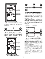
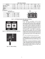
Fig. 87. Connect the 4-20 mA terminal to terminal TB3-9 and
connect the SIG COM terminal to terminal TB3-11. See
Fig. 89.
Fig. 89 — Indoor CO
2
Sensor (33ZCSENCO2)
Connections
Refer to PremierLink Controller Installation, Start-up, and
Configuration Instructions, for detailed configuration informa-
tion.
OUTDOOR AIR QUALITY SENSOR (P/N 33ZCSENCO2
PLUS WEATHERPROOF ENCLOSURE) — The outdoor
air CO
2
sensor is designed to monitor carbon dioxide (CO
2
)
levels in the outside ventilation air and interface with the venti-
lation damper in an HVAC system. The OAQ sensor is pack-
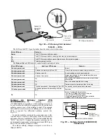
aged with an outdoor cover. See Fig. 90. The outdoor air CO
2
sensor must be located in the economizer outside air hood.
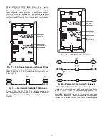
Fig. 90 — Outdoor Air Quality Sensor Cover
Wiring the Outdoor Air CO
2
Sensor (Unit Sizes 08-14)
—
A
dedicated power supply is required for this sensor. A two-wire
cable is required to wire the dedicated power supply for the
sensor. The two wires should be connected to the power supply
and terminals 1 and 2.
To connect the sensor to the control, identify the positive (4
to 20 mA) and ground (SIG COM) terminals on the OAQ sen-
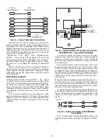
sor. See Fig. 87. Connect the 4 to 20 mA terminal to the TB1-
13 terminal of the 50TC. Connect the SIG COM terminal to the
TB1-11 terminal of the 50TC. See Fig. 91.
Fig. 91 — Outdoor CO
2
Sensor Connections
Wiring the Outdoor Air CO
2
Sensor (Unit Size 16)
—
A
dedicated power supply is required for this sensor. A two-wire
cable is required to wire the dedicated power supply for the
sensor. The two wires should be connected to the power supply
and terminals 1 and 2.
To connect the sensor to the control, identify the positive (4
to 20 mA) and ground (SIG COM) terminals on the OAQ sen-
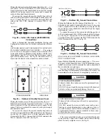
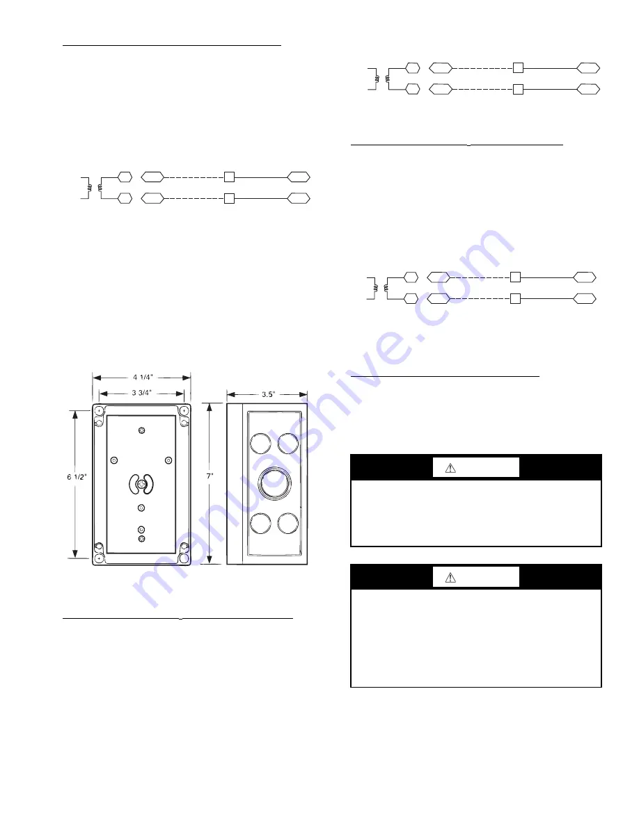
sor. See Fig. 87. Connect the 4 to 20 mA terminal to the TB3-
13 terminal of the 50TC. Connect the SIG COM terminal to the
TB3-11 terminal of the 50TC. See Fig. 92.
Fig. 92 — Outdoor CO
2
Sensor Connections
SPACE RELATIVE HUMIDITY SENSOR OR HUMIDI-
STAT CONNECTIONS
Space Relative Humidity Sensor connections
—
The acces-
sory space relative humidity sensor (33ZCSENSRH-01) is in-
stalled on an interior wall to measure the relative humidity of
the air within the occupied space.
The use of a standard 2 X 4 inch electrical box to accommo-
date the wiring is recommended for installation. The sensor can
be mounted directly on the wall, if acceptable by local codes.
If the sensor is installed directly on a wall, install the humid-
ity sensor using 2 screws and 2 hollow wall anchors (field sup-
plied). Do not over tighten screws. See Fig. 93.
SEN
J5-5
J5-3
COM
9
11
TB3
TB3
IAQ Sensor
PL
24 VAC
COVER REMOVED
S
IDE VIEW
CAUTION
UNIT DAMAGE HAZARD
Failure to follow this caution may result in permanent dam-
age to the sensor.
DO NOT clean or touch the sensing element with chemical
solvents as they can permanently damage the sensor.
CAUTION
UNIT PERFORMANCE HAZARD
Failure to follow this caution will result in inaccurate sen-
sor readings.
DO NOT mount the sensor in drafty areas such as near
heating or air-conditioning ducts, open windows, fans, or
over heat sources such as baseboard heaters, radiators, or
wall-mounted dimmers. Sensors mounted in those areas
will produce inaccurate readings.
S
EN
J5-2
J5-
3
COM
1
3
11
TB1
TB1
PL
OAQ
S
en
s
or/RH
S
en
s
or
24 VAC
SEN
J5-2
J5-3
COM
13
11
TB3
TB3
OAQ Sensor
PL
24 VAC
Summary of Contents for Carrier WeatherMaker 50TC A08 Series
Page 4: ...4 Fig 2 Unit Dimensional Drawing Size 08 09 12 Units...
Page 5: ...5 Fig 2 Unit Dimensional Drawing Size 08 09 12 Units cont...
Page 6: ...6 Fig 3 Unit Dimensional Drawing Size 14 Unit...
Page 7: ...7 Fig 3 Unit Dimensional Drawing Size 14 Unit cont...
Page 9: ...9 Fig 4 Unit Dimensional Drawing Size 16 Unit cont...
Page 13: ...13 Fig 8 Roof Curb Details Size 16 Unit...
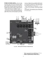
Page 50: ...50 Fig 73 50TC 16 Control Box Component PremierLink Locations...
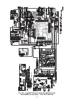
Page 51: ...51 Fig 74 Typical PremierLink Control Wiring Diagram...
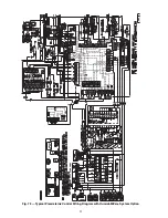
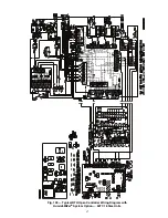
Page 52: ...52 Fig 75 Typical PremierLink Control Wiring Diagram with Humidi MiZer System Option...
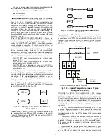
Page 64: ...64 Fig 106 Typical RTU Open Controller Wiring Diagram 50TC 08 14 Size Units...
Page 65: ...65 Fig 107 Typical RTU Open Controller Wiring Diagram 50TC 16 Size Unit...

