P/N 3101794-EN
• REV 03 • ISS 15FEB16
1 / 2
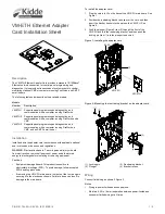
VM
-ETH Ethernet Adapter
Card Installation Sheet
Description
The
VM
-ETH
Ethernet Adapter Card provides a standard 10/100BaseT
Ethernet network connection for
control
panel programming and
diagnostics. It also provides
transmission of system events to central
monitoring stations (CMSs), computers running FireWorks, and SMTP
email servers.
The
following
table below describes the available
models
.
Models
Number
Description
VM
-ETH1
Supports panel programming and diagnostics, and
communication with a computer running FireWorks
VM
-ETH2
Supports panel programming and diagnostics, and
communication with a computer running FireWorks and
a
CMS
VM
-ETH3
Supports panel programming and diagnostics, and
communication with a
computer running
FireWorks,
a
CMS, and
an
SMTP email server
Installation
Install and wire the
adapter
card in accordance with applicable national
and local codes, ordinances, and regulations.
WARNING:
Electrocution hazard. To avoid personal injury or death
from electrocution, remove all sources of power and allow stored
energy to discharge before installing or removing equipment.
Cautions
•
Equipment damage hazard. This product is sensitive to
electrostatic discharge
(ESD). To avoid damage, follow accepted
ESD handling procedures
.
•
If removing the VM
-
CPU main board, first pull out the four plungers
securing it to the electronics chassis. Failure to do so can result in
damage to the main board.
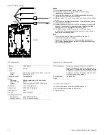
To install the adapter card:
1.
Plug the card into J3 on the back of the VM
-
CPU main board. See
Figure
1.
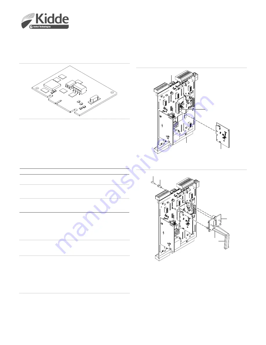
2.
Position the restraining bracket
recess
over the card, and then
insert the bracket hooks into the slots on the VM
-
CPU. See
Figure
2.
3.
Push the plunger (Figure
2
, item 2) through the front of the
VM
-CPU
and into the restraining bracket, and then
push
the
locking pin (item 1) into the plunger to secure it.
Figure 1: Installing the adapter card
Figure 2: Mounting the restraining bracket on the adapter card
(1)
Locking pin
(2)
Plunger
(3)
Restraining bracket
(4)
Bracket recess
Wiring
Connect field wiring as shown if Figure
3.
Notes
•
Wiring is power
-
limited
and unsupervised
.
•
Maintain 0.25 in. (6 mm) separation between power
-
limited and
nonpower
-
limited wiring at all times.
RJ-45
J3
VM-CPU
VM-ETH
(3)
(4)
(2)
(1)


