background image

 
USER’S MANUAL NO. 990-606


REVISION B: February 2000


OPERATION AND MAINTENANCE MANUAL 

FOR THE 

9100 SERIES SEMI-AUTOMATIC 

HIGH PRECISION 

REFLOW SOLDERING SYSTEM 


Summary of Contents for 9100 Series

Page 1: ...USER S MANUAL NO 990 606 REVISION B February 2000 OPERATION AND MAINTENANCE MANUAL FOR THE 9100 SERIES SEMI AUTOMATIC HIGH PRECISION REFLOW SOLDERING SYSTEM...

Page 2: ...herein are the proprietary work of UNITEK MIYACHI CORPORATION and may not be reproduced copied exhibited or otherwise used without the written authorization of UNITEK MIYACHI CORPORATION Printed in t...

Page 3: ...rmation needed to properly and safely operate and maintain Unitek Precision System s 9100 Series Reflow Soldering System The System consists of three major units the workstation the Uniflow Pulsed The...

Page 4: ...nuals before attempting to use the workstation Procedures other than those described in these manuals or not performed as prescribed in them may expose personnel to electrical burn or crushing hazards...

Page 5: ...1 Space Requirements 2 1 Power Requirements 2 1 Compressed Air Requirements 2 1 User Manufactured Jigs Mounting Hole Requirements 2 1 CHAPTER 3 Operating Instructions 3 1 Section I Operating Precautio...

Page 6: ...cess Panels and Electrical Connectors 1 6 3 1 Installing a Typical Jig 3 3 3 2 Making the Unislide Adjustments 3 4 3 3 Making Co Planarity Adjustment 3 5 3 4 Aligning Items to be Bonded with Micromete...

Page 7: ...le allows simultaneous loading and bonding operations Flexible programming for up to six product nests and three different product types Software is configured to allow automatic changeover between pr...

Page 8: ...g System comprises three major units the actual workstation with its rotary turntable workstation a Uniflow Pulsed Thermode Control Uniflow and a bonding head In the separate manual for the bonding he...

Page 9: ...eads 87SA 24 84SA 24 or 180SA 24 You will receive the respective manual for your module as shown in table 1 1 as part of your technical manual suite Related manuals which you may wish to procure from...

Page 10: ...SET switch is pressed 4 CONTROL OFF switch Red pushbutton Used to remove power to the control circuits and electrical sensors and switches 5 CONTROL ON switch indicator Green pushbutton with built in...

Page 11: ...ch is a pair as shown in figure 1 3 Figure 1 3 Workstation Tabletop 1 READY TO INDEX switches indicators Green pushbuttons with built in indicators The two green indicators light when the bonding head...

Page 12: ...access points are monitored with interlock switches to prevent operation of the unit when they are opened unless the GUARD OVERRIDE key switch is activated On the right hand side of the workstation a...

Page 13: ...in 1245 mm 17 in 432 mm Depth 43 in 1092 mm 17 in 432 mm Height 60 in 1524 mm 28 in 702 mm Additional space required to open access doors The floor surface must be able to support the weight of the w...

Page 14: ......

Page 15: ...indicator will warn the operator of this condition With the GUARD OVERRIDE activated the safety shields may be lifted with full operation unhindered Therefore the operator is in danger of burning crus...

Page 16: ...It should only be done by a trained individual wearing safety glasses and no loose clothing or jewelry Set up consists of three actions installing the necessary jigs aligning the Bonding Head and ther...

Page 17: ...sure that the identical jigs pairs are opposite each other in identically marked locations 5 Repeat step 1 until the next location at which a jig will be installed is in front of you Repeat step 2 6...

Page 18: ...iflow front panel is in the NO HEAT position 4 Press the blue MANUAL BOND pushbutton to cycle the Bonding Head Remove the pressure sensitive paper and observe if the pressure was equally distributed f...

Page 19: ...d on perform the turn on procedure described above 4 Turn on the Uniflow as described in the Uniflow User s Manual 5 If you wish to keep track of the number of items bonded press the reset switch on t...

Page 20: ...remove the two bonded items inspect them and insert two new items to be bonded 11 Continuously repeat steps 9 and 10 until your job is complete To remove the final piece simultaneously press the whit...

Page 21: ...crushing and entanglement hazards Wear safety goggles any time you are operating the workstation with the safety shield open Before performing operator maintenance read the separate manuals on the Uni...

Page 22: ...with air under pressure 5 Clean filter by blowing off dust particles with low pressure air 6 Reassemble the vacuum generator and reinstall it by reversing the above steps Grease Rotary Table Ring Gea...

Page 23: ...VACUUM GENERATOR UNSCREW FITTING FROM HUB REMOVE 12 CAP SCREWS CAUTION EITHER PROP UP OR RETRACT BONDING HEAD TO PREVENT DAMAGE FROM ROTARY TABLE CAUTION DO NOT BANG PROXIMITY SENSOR WHEN REMOVING RO...

Page 24: ...is too much play in the Unislide tighten the gib strip screw figure 4 7 Clean Bonding Edge of Thermode Complete instructions for the care of thermodes are contained in the appropriate Weld Head User s...

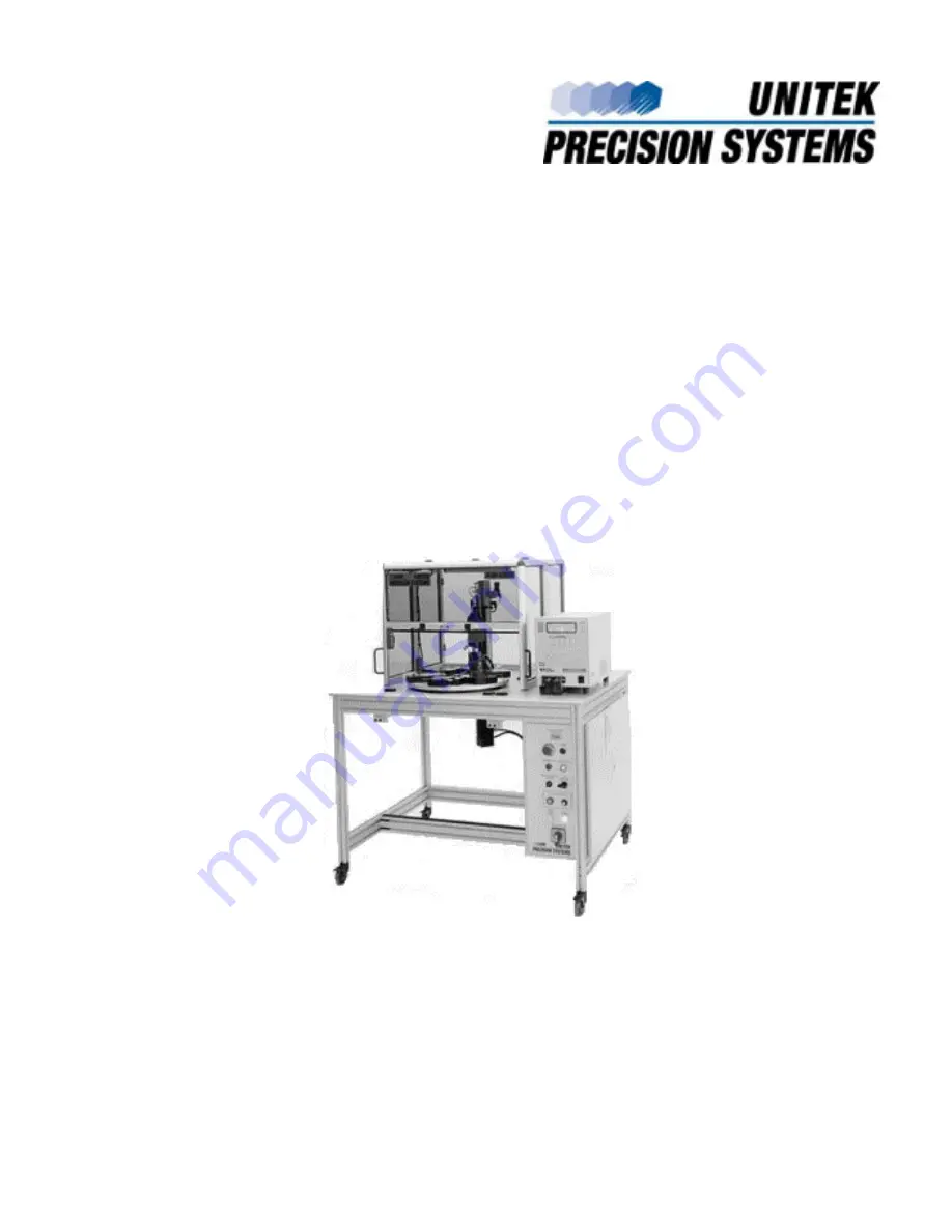
Page 25: ...9100 SERIES REFLOW SOLDERING SYSTEM 990 606 A 1 APPENDIX A SPECIFICATIONS...

Page 26: ...sed air Requirements 80 100 p s i 5 6 7 0kg cm2 minimum Operating Environment 60 113 F 15 5 45 C 93 Relative Humidity maximum at 104 F 40 C Table Speed 1 5 seconds per 180 Rotation speed between matin...

Page 27: ...APPENDIX A SPECIFICATIONS 9100 SERIES REFLOW SOLDERING SYSTEM 990 606 A 3 Figure A 1 Outline Drawing of Workstation 49 1245mm 43 1092mm 60 1524mm...

Page 28: ...APPENDIX A SPECIFICATIONS 9100 SERIES REFLOW SOLDERING SYSTEM A 4 990 606 84 87 HEAD Figure A 2 Jig Specification Sheet 1 of 4...

Page 29: ...APPENDIX A SPECIFICATIONS 9100 SERIES REFLOW SOLDERING SYSTEM 990 606 A 5 180 HEAD Figure A 2 Jig Specification Sheet 2 of 4...

Page 30: ...APPENDIX A SPECIFICATIONS 9100 SERIES REFLOW SOLDERING SYSTEM A 6 990 606 JIG ENVELOPE CONDITIONS FOR 84 87 HEAD CONDITIONS FOR 180 HEAD Figure A 2 Jig Specification Sheet 3 of 4...

Page 31: ...EAD TYPE 84 87 180 DIM A DIM B DIM C DIM D DIM W DIM L DIM H 12 09 MAX AT FRONT 12 09 2 322 3 109 1 181 2 362 12 09 MAX AT FRONT 12 09 MAX AT FRONT 12 09 12 09 2 322 3 109 1 181 2 362 3 109 2 322 1 18...

Page 32: ......

Page 33: ...5 D Definitions Caution iv Warning iv Description of system 1 1 Doors access 1 6 E Electrical Connectors 1 6 Requirements 2 1 A 2 Emergency shutdown 3 6 Equipment Operation 3 2 Set up 3 2 Establishin...

Page 34: ...d adjust 4 4 Clean bonding edge of thermode 4 4 Clean vacuum generator filter 4 2 Grease rotary table ring gear and refill lubricators 4 2 R Record of revisions ii Reflow schedule 3 5 Requirements ope...

Reviews: