21
3 Electrical Installation
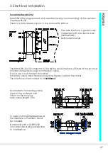
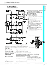
EMC Advice
The devices adhere to the EU guidelines 89/336/EWG and the technical standards
EN 61000-2 and 61000-4 provided that the following conditions are observed:
- The device is conductively mounted on a 500x500x5 mm bright
aluminium mounting plate-
The mounting plate must be connected to -U
B
using a 10mm² wire.
- The motor housing must be connected to -U
B
using a 10mm² wire.
- The device ground X-AGND must be connected to the mounting plate
using a 1.5mm² wire.
- The housing must be connected to the mounting
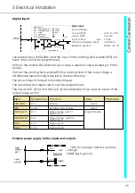
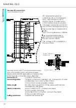
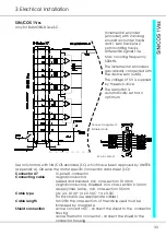
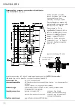
Connection of the control conductors:
All control conductors must be shielded. Analogue signal lines must be twisted and
shielded. The shield must have surface-to-surface contact with the mounting plate.
Battery connection:
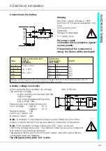
48V dc voltage
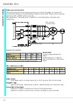
Motor connection:
After having been mounted in machines and installations the
operation of the device must not be started until the machine
or the installation has been approved of the regulations of the
EC machine guideline 89/392/EWG and the EMC guideline
89/336/EWG.
A manufacturer’s declaration can be asked for.
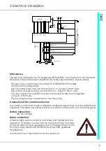
Battery voltage
double grounding
for >2m
Housing
CNC/PLC
Shield
on the connector
housing
15pin connector
double grounding
for >2m
Motor chokes
only for a conductor length of >25m
Machine frame
M
3 bl
RLG
bl
X9
CAN-
BUS
X8
INC-
OUT
X1:7
FRG
RUN
X1:8
analogue
com.value
X1:9
GND
XB:1
XB:5
X7
XB:2
XB:3
XB:4


