25
3 Electrical Installation
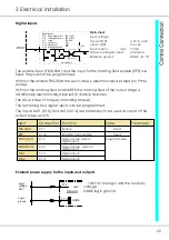
Digital inputs
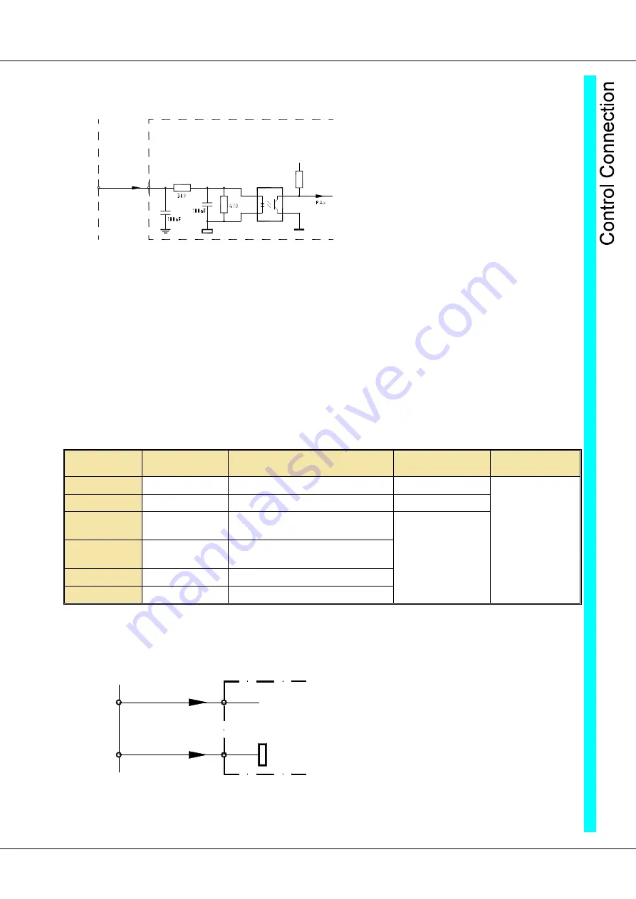
The enable input (FRG/RUN) and the input for the rotating field enable (RFE) are
fixed, they cannot be programmed.
Without the enable FRG/RUN the servo-drive is electronically disabled (no PWM
pulses).
Without the rotating field enable RFE the rotating field of the output stage is
additionally electronically disabled (2
nd
disable channel).
The drive is free of torque (no holding torque).
The remaining four digital inputs can be programmed.
The inputs LMT1 (X1:5) and LMT2 (X1:6) are preferably to be used as inputs of the
output stage switch.
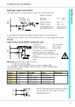
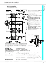
External power supply for the inputs and outputs
+24V for the logic and the auxiliary
voltage
GNDE logic ground
Logic
voltage
24V=
Logic
ground
GNDE
DS400
+24V
X1:4
X1:10
Digital input
10 to 30V=
Digital inputs
X1:5
X1:6
X1:7
X1:11
X1:12
X1:18
Output stage switch 1
output stage switch 2
enable
digital input 1
digital input 2
rotating field-enable
END1/LMT1
END2/LMT2
FRG/RUN
DIN1
DIN2
RFE
DSxx/BAMO-D
VCC
Opto-input
Input voltage
H-level (ON)
+10V to +30V
L-level (Off)
0 to +6V
Input current
max. 7.5 mA
Nominal voltage/current
+24V/6mA
Referenc ground
GNDE (X1:10)
Input
Connection Function
State
Parameter
FRG/RUN
X1:7
Enable
fixed
RFE
X1:18
Rotating field enable
fixed
END1/LMT1
X1:5
Output stage switch 1
Digital input
programmable
END2/LMT2
X1:6
Output stage switch 2
Digital input
DIN1
X1:11
Digital input1
DIN2
X1:12
Digital input2


