background image

30

BAMOBIL D3.2

CAN-BUS

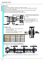
The CAN-BUS is a digital connection to the CNC control.

Optimum conditions are achieved with CNC controls and CAN components of

LABOD electronic or CAN Open.

Programming and operation by means of the control panel via the CAN-BUS.

Interface complies with the standard ISO 11898.

Adjustment and programming see Manual DS-CAN.

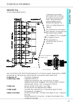
CAN-BUS connection with several BAMOBIL-D3

Master

Address xx

Address xx

Address xx

Terminating resistor at the end of the bus line > 120Ohm between the CAN-H and

CAN-L

The BUS interface is galvanically

isolated from the internal device

voltage.

.

The voltage is supplied via an

internal, isolated DC-DC

converter or via the BUS cable.

CAN-V+ 9 to 15V=

Designation

Connect. no

cable

color

cable

no.

CAN-V+

9

brown

1

CAN-GND

3

white

4

(PE)

CAN-H

7

green

3

CAN-L

2

yellow

2

CAN-BUS cable

Use a shielded bus conductor with a low

shielding capacity.

Signal plus GND (+supply).

D-connector with a metal or metallized

housing. LiYCY 4x0.25+shield.

Summary of Contents for Bamobil D3.2

Page 1: ...Version 0808 2 V3 Manual Bamobil D3 2 Digital Battery Drive for EC Servo Motors Industrie Elektronik Tel 07195 9283 0 Fax 07195 928329 email info unitek online de Http www unitek online de...

Page 2: ...sions Control panel 13 Dimensions Additional cooling unit 14 15 3 Electrical installation CE and safety advice 17 Circuit diagrams 18 19 Connection diagram 20 EMC 21 Connectors 22 Battery connection 2...

Page 3: ...1 Basic Information 3...

Page 4: ...ss dc motors for industrial applications Protection rating IP40 Connection only to batteries Standards and guidelines The device and its associated components can only be installed and switched on whe...

Page 5: ...ectronic drives and their software should only be carried out in accordance with the programming advice should only be carried out in accordance with health and safety guidelines CE After having been...

Page 6: ...is proportional to the torque and the voltage is proportional to the speed The speed is steadily controlled up to the current limit max torque In case of an overload the speed drops and the current re...

Page 7: ...es and installations such as assembly machines metal working machines food processing machines robots and handling systems conveyors stone working machines and for many other battery supplied applicat...

Page 8: ...and industrially standardised are used SMD equipment 7 segment LED displays Characteristics battery powered or dc connection 24V to 48V 24V to 120V independent auxiliary voltage connection 24V digita...

Page 9: ...V programmable up to max 68V Input fuse A 80 160 250 250 500A Weight kg 5 5 5 8 6 8 6 8 6 8 Dimensions hxwxd mm 244x194x90 Unit size 2 2 2 2 2 For battery voltages up to 120V Power supply connection...

Page 10: ...performance reduced by 2 o C Storage temperature 30o C bis 80o C Humidityrating Klasse F rel humidity 85 no condensation Site of installation 1000m a m s l 100 1000m with power derating 2 100m Ventila...

Page 11: ...on air min 100mm If the heat is not dissipated sufficiently the device switches off via its temperature watchdog Any bore hole dimensions for the fixation of the device must be taken from the dimensio...

Page 12: ...the rear panel of the switch cabinet 4mm bright steel the cooling capacity of the plate corresponds to a continuous current of 35A S1 duty when the plate is 10mm thick a continuous current of 50A when...

Page 13: ...13 2 Mechanical Installation Dimensions Control tpanel The control panel is connected with the control unit via the CAN BUS act comm...

Page 14: ...al cooling unit for control panel mounting Fixing bore hole dimensions see basis device Fixing screws M5x110mm Vertical mounting position performance reduced by 20 if the mounting position is horizont...

Page 15: ...hanical Installation Dimensions Additional cooling unit to be inserted Control panel break through Fixing screws M5x30mm Mounting depth without connector Enough space for the ventilation air must be p...

Page 16: ...16 BAMOBIL D3 2...

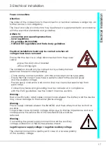
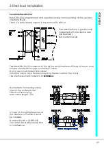
Page 17: ...th those indicated on the type plate Ensure that the correct fuses have been provided for the power supply and the auxiliary voltage Power supply conductors and control lines must be routed separately...

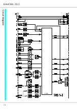
Page 18: ...18 BAMOBIL D3 2 Core REFERENCE...

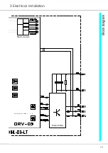
Page 19: ...19 3 Electrical Installation Mains module Output stage 6x op coup driver...

Page 20: ...PC COMx Battery voltage D1 braking current diode EC Motor Encoder Encoder Feedback Safety circuit emergency stop Control Drive enable Analogue com value 10V Logic GND Logic output Logic input Analogue...

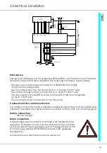
Page 21: ...must be shielded Analogue signal lines must be twisted and shielded The shield must have surface to surface contact with the mounting plate Battery connection 48V dc voltage Motor connection After ha...

Page 22: ...e switch Drive enable Analogue input 1 Logic zero Digital input Digital output Analogue input Digital output Rotating field enable Analogue output Analogue zero Supply GND Channel N Channel B Channel...

Page 23: ...to 10m Auxiliary voltage connection Mains potential free auxiliary dc voltage 24V 10 2A The auxiliary voltage is galvanically connected with the logic voltage has internal regenerating fuses has an EM...

Page 24: ...cable cross section Motor choke Only necessary for a shield capacity of 5nF Approx 25m motor cable Magnetic rings against HF failures of the sensor systems Slide the rings onto the motor lines Connect...

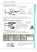
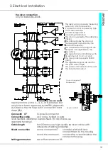
Page 25: ...e inputs and outputs 24V for the logic and the auxiliary voltage GNDE logic ground Logic voltage 24V Logic ground GNDE DS400 24V X1 4 X1 10 Digital input 10 to 30V Digital inputs X1 5 X1 6 X1 7 X1 11...

Page 26: ...FRG RUN signal in the 1st disable channel to disable the PWM pulses in the processor there is no RFE signal in the 2nd disable channel to disable the PWM pulses at the output of the processor Restart...

Page 27: ...State signal via seven segment LED display In case of failures the contact is open BTB opens red LED open relay contact in case of error messages in case of under voltage of the auxiliary voltage 20V...

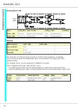
Page 28: ...ion of the motor can either be changed by swapping the connections at the differential input or by means of a logic input or by programming The analog inputs can be assigned to different functions Wit...

Page 29: ...modem cable Do not use a null modem link cable Install the cable only after disconnecting the device from the mains The interface is hard coded to 115200Baud In case of strong interferences at the int...

Page 30: ...L D3 Master Address xx Address xx Address xx Terminating resistor at the end of the bus line 120Ohm between the CAN H and CAN L The BUS interface is galvanically isolated from the internal device volt...

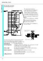
Page 31: ...he digitalized signals are used for the polar wheel angle the position and speed control and the incremental output Use only motors with a 2 4 6 or 8 pole resolver which have been approved by UNITEK A...

Page 32: ...cross connector X7 connect the shield to the connector housing across the motor connector connect the shield to the connector housing Setting parameter see software Manual DS Encoder TTL connection on...

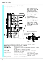
Page 33: ...pproved by UNITEK Appendix A Observe the motor specific connection data sheet SC Connector X7 15 pole D connector Connecting cable 4 signal conductors twisted and shielded min cross section 0 14mm 2 s...

Page 34: ...the tacho center point to X7 1 Use only motors with rotor position encoders bl which have been approved by UNITEK Appendix A Observe the motor specific connection data sheet bl Connector X7 15 pole D...

Page 35: ...nnector X8 is connected as input or output default Output X8 pin 6 not connected or bridged with GND Input X8 pin 6 bridged with 5V X8 1 9 pole D connector M pins connector assignment soldered side No...

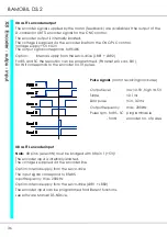
Page 36: ...a4 Bit1 for IN it corresponds to the encoder no of pulses Pulse signals motor revolving clockwise Output level low 0 5V high 4 5V Slope 0 1ms Zero pulse min 0 2ms Output frequency max 200kHz Pulse rpm...

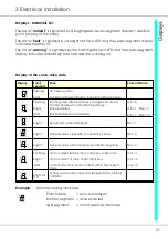
Page 37: ...rdware failure Flashing Bright dark Starting state after reset auxil voltage 24V off on The first enable stops the flashing display Drive enabled Drive disabled not enabled OK 0 OK 1 ENA 1 OK 1 ENA 0...

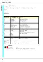
Page 38: ...faulty 5 POWER VOLTAGE Power voltage missing 6 MOTOR TEMP Motor temperature too high 7 DEVICE TEMP Device temperature too high 8 OVER VOLTAGE Over voltage 1 8 x UN 9 I_PEAK Over current 300 A RACE AWA...

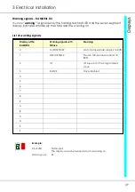
Page 39: ...e and the warning no List of warning signals Display at the BAMOBIL Warning signals with NDrive Meaning 0 MOTOR TEMP Motor temperature superior to 80 1 DEVICE TEMP Device temperature superior to 80 2...

Page 40: ...irs effected by the Buyer or a third party non observance of the manual which is included in all consignments non observance of the electrical standards and regulations improper maintenance acts of na...

Reviews: