background image


21

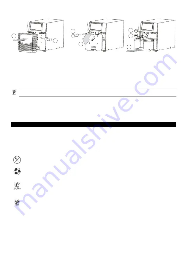
Please follow the steps 1-8 to replace the new battery: 


1

2

3

6

7

5

4


9. 

Use “cross” screw driver to remove the screws of the front panel.  

10.  Pull the front panel out from the UPS.  
11.  Remove the 4 screws as indicated above.  
12.  Pull down the battery fastened plate as indicated.   
13.  Pull out the battery tray a little.  
14.  Remove the battery negative (-) end of the battery and make sure it won’t be short with the battery positive (+).  
15.  Remove the battery positive end, and then pull out the battery tray completely for new battery replacement.  
16.  Repeat all the procedures in reverse way to finish the replacement task. 


Please do not be reversed the RED (+) and black (-) of battery wire when you connect them to the terminal of 
battery. • Once the battery is disconnected, the loads are not protected from power outages 

4.2 Storage Instructions


The UPS should be stored in a cool dry location. Make sure the battery is fully charged before the UPS is stored. For 
extended storage in moderate climates, the battery should be charged for 12 hours every 6 months by plugging the 
power cord into the wall receptacle and turning on the main switch. Repeat every 3 months in high temperature 
locations (more than 30°C). 
 

5. Troubleshooting


The TROUBLESHOOTING TABLE in the next page covers most of the difficulties that you may encounter under 
normal working conditions. If the UPS fails to operate properly, please review the following steps before calling the 
repair center: 
1. Is the UPS plugged into a proper working outlet? 
2. Is the line voltage within the specified rating? 
3. Does the fuse on the rear panel need to be replaced? 


  Please do not open the metal cover. 
  There are no user serviceable parts inside 


  The batteries contained in this UPS are recyclable. 
  The batteries contain lead and pose a hazard to the environment and human health if not disposed of 

properly. 


  Do not open or mutilate the batteries. They contain an electrolyte which is toxic and harmful to the skin 

and eyes. 

  A battery can present a risk of electrical shock and high short circuit current. When replacing batteries, 

wrist watches and jewelry such as rings should removed. Use tools with insulated handles. 


  Please note the following information when you call for service: 
  Model Name and Serial Number. 
  Date and place of purchase 
  Full description of problem. 


Summary of Contents for DELTA 800

Page 1: ...anuel de l utilisateur Manual del usuario User s manual DELTA 800 1100 1400 2200 3000 Onduleur Online System 800 3000 VA SAI Online System 800 3000 VA 800 3000 VA Online System UPS www unitek power co...

Page 2: ...2...

Page 3: ...nnect es n exc de pas les 3 5 mA Cet appareil g n re utilise et peut mettre des fr quences radio S il n est pas install conform ment aux instructions il peut provoquer des interf rences au niveau des...

Page 4: ...eur trop faible corrig 11 Voltage secteur trop fort corrig 12 Sortie onduleur 13 Erreur de polarit ou de mise la terre 14 Surcharge 15 Taux de charge de l onduleur des batteries 16 Affichage taux de c...

Page 5: ...batterie quand le voltage ou la fr quence du secteur sortent des plages de tol rance Des alertes visuelles et sonores sont alors d clench es L onduleur fournit alors un courant r gul gr ce ses batter...

Page 6: ...t 2 6 Indicateurs visuels et sonores bips Etat Mode Normal secteur normal Erreur de polarit ou de mise la terre 1 bip 2 secondes Mode Batterie d faut du secteur 1 bip 1 secondes Mode Batterie d faut d...

Page 7: ...ois en pays chauds 5 R solution de probl me La table de r solution de panne ci dessous couvre la plupart des difficult s que vous pourrez rencontrer lors d une utilisation normale de votre onduleur Si...

Page 8: ...t be turned on Computer input power cord is loose or not connected Reconnect computer input power cord correctly Battery is not fully charged or battery is dead or weak Recharge the battery for 4 hou...

Page 9: ...Ah x2 12V 9Ah x2 12V 7Ah x4 12V 9Ah x4 Replacement utilisateur OUI Batterie Temps de recharge 2 4 heures 90 Mode Normal 110 pendant 10 minutes puis arr t Prot contre les surcharges Mode Batterie 110 p...

Page 10: ...10...

Page 11: ...as est n apagadas durante la instalaci n Este equipo genera utiliza y puede irradiar energ a en el espectro de radio frecuencia Si no es instalado y utilizado siguiendo las instrucciones este equipo p...

Page 12: ...ndicaci n nivel de bater a Panel trasero 1 Puerto RJ45 2 Interruptor DIP 3 Puerto de comunicaci n USB 4 Puerto de comunicaci n RS232 5 Bot n de reajuste de CPU Interno Presione para apagar 6 Interrupt...

Page 13: ...lmente cargadas Tambi n regula el voltaje de salida para que se mantenga en el rango requerido y a su vez a sla la carga de picos de corriente y ruido que pueda venir del AC comercial Modo Bater a El...

Page 14: ...e los cuales est trabajando y apague el ordenador Despu s apague el SAI para conservar la bater a para su uso posterior y tests adicionales Reponga la energ a el ctrica al equipo conectado reenchufand...

Page 15: ...r el UPS Para guardar el UPS por largo tiempo en climas moderados cargue las bater as por 12 horas cada tres meses simplemente conectando el UPS y encendiendo el interruptor principal Repita cada dos...

Page 16: ...9Ah x2 12V 7Ah x4 12V 9Ah x4 Reemplazable por el usuario Yes Bater a Tiempo de recarga 2 4 horas para 90 Modo normal 110 por 10 minutos y apagado Protecci n de sobrecarga Modo bater a 110 por segundos...

Page 17: ...t installed and used in accordance with the instructions this unit may cause harmful interference to radio communications However there is no guarantee that interference will not occur in a particular...

Page 18: ...load 15 Load Battery Level 16 Load Battery Level Indication control button Rear panel 1 RJ11 RJ45 Port 2 DIP Switch 3 USB Communication Port 4 RS232 Communication Port 5 Internal CPU Reset Button pres...

Page 19: ...ught by the mains On Battery Mode The UPS operates on battery when the line voltage or frequency has fallen outside the limits The user is alerted of this mode of operation by visual and audible indic...

Page 20: ...est 2 6 Audible Visual Indicators Buzzer Operating Status Normal mode Mains normal Polarity Error ground fault 1 beep every 2 seconds Battery mode Mains failure 1 beep every second Battery mode Mains...

Page 21: ...g the power cord into the wall receptacle and turning on the main switch Repeat every 3 months in high temperature locations more than 30 C 5 Troubleshooting The TROUBLESHOOTING TABLE in the next page...

Page 22: ...computer can t be turned on Computer input power cord is loose or not connected Reconnect computer input power cord correctly Battery is not fully charged or battery is dead or weak Recharge the batt...

Page 23: ...ge 12V 7Ah x2 12V 7Ah x2 12V 9Ah x2 12V 7Ah x4 12V 9Ah x4 User s Replacement Yes Battery Recharge time 2 4 hours to 90 Normal mode 110 for 10 minutes then shutdown Overload prot Battery mode 110 for s...

Page 24: ...24 w w w u n i t e k p o w e r c o m v 2 1 0504...

Reviews: