19 01/2018 - V1
Classic
P3 60-150 A
Commissioning
Co
m
m
iss
io
ni
ng
6
Commissioning
6.1
Commissioning
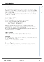
Connect the drive in accordance with the P3 manual and the control electronics manual
(e.g. REG).
Please observe in particular:
Check the power supply voltage with that specified on the type plate
Insert the correct fuses according to the technical data (see contents).
Check the field voltage connection and the motor and tacho connections!!!
For 60Hz applications adjust the switch S2, contact 1 to position 'ON'.
Commissioning
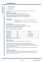
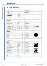
Basic connections:
Mains supply, field, tacho, or armature feedback, drive
enable,
command value
.
For armature voltage control the tacho watchdog must be switched off.
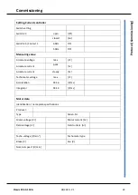
Drive enable switch
open or drive enable voltage 0V/command value voltage 0V
Adjust switch S9 to tacho voltage, adjust to 0 for armature voltage control.
Adjust switch S4 to position 2, switch S5 to position 6.
Adjust the potentiometer
I
max1 to left full scale
Adjust the potentiometer
I
max2 to approx. 10%.
Potentiometer
Xp
to 50%
Potentiometer
I
D
= 100 %
Potentiometer
IxR
= left full scale
Potentiometer
n
max
= left full scale
Potentiometer
INT
= left full scale
DS1:K1, DS2:K4
ON
Bridges R13 and R14 soldered-in (only tacho)
Apply the voltage
The LED L3 (BTB) and the LED L7 (standstill) must light. All other LEDs are off.
Close the switch 'drive enable' or apply a drive enable voltage of >10V
The LEDs L1 and L2 must also light. The drive must be at a standstill or turn slowly (offset
If the drive accelerates in the correct direction, the polarity of the tacho voltage and the armature
voltage feedback must be changed.
If the drive accelerates in the wrong direction, the polarity of the armature or the field must be
changed.
Command value voltage
Increase the command value voltage to 10 %. The drive must accelerate to approx. 10% of the
speed. If the rotation direction is wrong, change the polarity of the tacho and the field
or
the
polarity of the tacho and the armature.

