background image

6 Getting Started

TV3.2

31

G

e

tt

in

g

S

ta

rt

e

d

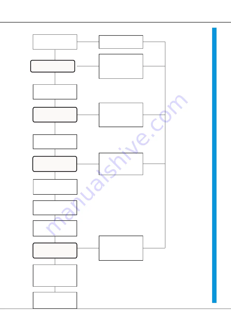
basical set-up

switch on power supply

nominal value 0V

switch on enable

LED green dark

auxiliary power voltage missed

motor runs quick

or vibrates

encoder or motor

connection wrong

switch off power supply

remove error

Increase nomimal value up

to10%

motor stands still

check nominal value

check motor line

motor runsrestless

reduce amplification Xp

adjust speed with n

max

to 10%

Increase nominal value to

100%

adjust speed with offset

to zero

speed is not adjustable

resistance R23 wrong

power voltage too low

current limit too small

adjust current limits

peak current with Imax

Continous current with I

D

to

motor dates

basic setup finished

optimize drive

fill in protocol

LED BTB green bride

motor stands still

or runs steady slowly

motor runs

steady with ca. 10%

motor runs

steady with ca. 10%

Summary of Contents for TV3.230 Series

Page 1: ...MANUAL Servo Drive TV3 230 xx for DC Servomotors with DC Tachometer TV3 230 Edition 0109...

Page 2: ...dvice 13 Connection with Isolation Transformer 14 Motor Power Connection 15 Connection 16 Speed Nominal Value 17 Current 18 Signals Ready for Operation Signal BTB 19 Analogue Measuring Outputs 19 Pin...

Page 3: ...6 EN61800 3 IEC UL IEC364 IEC 664 UL508C UL840 VDE regulations VDE100 VDE110 VDE160 T V regulations Regulations of Professional and Occupational bodies VGB4 The user has to assure that after a failure...

Page 4: ...ed back of the energy must be observed when braking in the dc bus especially where stroke or eccentric cycles are concerned The ballast circuit is designed for 3 on period higher cyclic durations can...

Page 5: ...in component insertation machines metall sheet working machines machine tools plastic working machines assembly machines knitting and sewing machines textile working machines grinding machines wood a...

Page 6: ...er semiconductors generous dimensioning only industrial standard components are used SMD basic insertion LED displays 4 digit binary switches for system setup precision potensiometers for fine adjustm...

Page 7: ...32x67x205 12TE 3HE 132x82x205 Mains module TVD3 230 Power supply V 1x oder 3x 230V plus 1x 20V Output voltage V max 320 Output current A max 30 Ballast circuitry with V 400 Ballast power W WS 50 6000...

Page 8: ...c mm Weight kg 2M5 4 4 2 5 60x 85x 65 0 7 2M6 8 8 2 5 70x 90x 75 1 2 2M7 12 12 1 5 80x 105x 86 1 4 Trafo Typ Trafo power VA Dimensions a b c mm Weight kg TE 8 2 100 85x 89x 82 2 0 TE 12 1 250 120x101x...

Page 9: ...2 Mechanical Installation TV3 2 9 Multi Axes Combination...

Page 10: ...all amount of energy The excess energy has to be converted into heat in the regenerative resistor The internal resistor is designed for drives without flyweights Always use external regenerative resis...

Page 11: ...3 Electrical Installation TV3 2 11 Connection Overview...

Page 12: ...Transistor Servo Drive TV3 230 12 Compact Device Connection Plan Multi axes Combination 230V 20V o 24V...

Page 13: ...nnected to mounting board with a 50mm long 4mm wire Rack gnd screw connected to mounting board with a 50mm long 4mm wire Connection one phase Trafo with filter type TE8 2 F to TE17 3 F linelength betw...

Page 14: ...transformer Notice rate contactor contacts according to transfomer inrush current delay action fuses before transformer fuse value according to transformer current quick fuses after transformer fuse v...

Page 15: ...10 25 0 5 automattion B A 6 10 10 25 Motor Power Connection cable No PE M1 M2 M3 connection PE bolt X3 1 X3 3 M3 3 motor cable with 5A 10A thermo break cross section 0 75 1 5 0 5 0 5 kable kind 2x mot...

Page 16: ...acts or reed relays Contact current 6mA Enable internal logical voltage internal logical voltage X1 1 15V 10mA contact chain between X1 1 and X1 2 Enable external logical voltage enable voltage 10 30V...

Page 17: ...inal value lines paired twisted and shielded Screen connection one sided Connection Nominal value voltage with internal supply nominal value X1 4 signal X1 7 GND bridge X1 6 X1 7 External nominal valu...

Page 18: ...0 up to 200 device rated current internal overcurrent control max 5sec Current limit input maximum input voltagel 10V input resistance 10 kW Internal attenuation with potentiometer Imax1 relay contact...

Page 19: ...ler motor stored overvoltage stored short circuit line to earth fault stored voltage error not stored intermediate circuit error not stored To reset store switch off on enable Caution Use BTB contact...

Page 20: ...compact device function clamp No motor 1 X3 1 free X3 2 motor 3 X3 3 power X3 4 voltage X3 5 auxiliary X3 6 voltage X3 7 Power connections plug in unit Function plug in connector clamp No intermediate...

Page 21: ...ion D1 green BTB D2 red fault Poti P5 Imax P4 ID P3 XP P2 nmax P1 Offset plug X1 1 15V X1 2 enable X1 3 10V X1 4 nom value X1 5 10V X1 6 nom value X1 7 GND X2 8 n actual value X2 9 I actual value X2 1...

Page 22: ...Transistor Servo Drive TV3 230 22 Block Diagram...

Page 23: ...D amplification P componentl resistance R9 poti P3 XP amplification I component condensator C4 zero balance poti P1 offset switch S1 function contact ON OFF current limit 2 internal external current a...

Page 24: ...ution control systems have to be optimized from inside to outside sequence current controller speed controller position controller Measuring values measuring value max measuring nominal value 10V X1 4...

Page 25: ...ustment with external resistor R TG tacho voltage x 1 2 8TG Fine adjustment with potentiometer nmax P2 nominal value of potentiometer adjust with 1V nominal value to 10 maximum speed adjust finely wit...

Page 26: ...Transistor Servo Drive TV3 2 26 Empty page...

Page 27: ...Nominal value Integrator Linear Integrator Time adjustment with resistor R11 INT 5 Adjustment TV3 2 27 Resistor Ohm Time sec...

Page 28: ...it can internally be reduced with Imax potentiometer continous current adjust motor protection adjustment for both momentum directions on motor nominal current with potentiometer ID P4 measure adjustm...

Page 29: ...tentiometer Xp clockwise until drive swings turn potentiometer Xp anticlockwise until the swinging is dying out turn Xp potentiometer further 2 positions anticlockwise Drive behaviour amplification to...

Page 30: ...case Mind connection advices basical connections power connections protection earth PE bolt mains 1x or 3x 230V motor 2x motor lines protective conductor screen transmitter connection mind motor speci...

Page 31: ...nominal value check motor line motor runsrestless reduce amplification Xp adjust speed with nmax to 10 Increase nominal value to 100 adjust speed with offset to zero speed is not adjustable resistanc...

Page 32: ...errupted motor speeds up tachometer polarity wrong tachometer connection interrupted motor runs restless amplification Xp toohigh nominal value failure amplifier switches to failure LED red bright ove...

Page 33: ...e to 10 increase amplification with Poti Xp until the drive swings afterwards rerduce until the drive runs smoothly adjust current limits with Poti Imax to peak current and Poti ID to steady current o...

Page 34: ...Transistor Servo Drive TV3 230 34 Signals...

Page 35: ...Controller Variable Components P component R9 Value I component C4 Value Poti positions Peek current Imax P5 Position Steady current ID P4 Position Amplification Xp P3 Position Speed nmax P2 Position...

Page 36: ...repairs effected by the Buyer or a third party non observance of the manual which is included in the all consignments non observance of the electrical standards and regulations improper maintenance ac...

Reviews: