background image

TELARIS

®

LOOP

UNITEST

®

Instruction Manual Cat. No. 8978

Summary of Contents for TELARIS LOOP

Page 1: ...TELARIS LOOP UNITEST Instruction Manual Cat No 8978...

Page 2: ...2...

Page 3: ...ement 8 6 2 Internal Mains Resistance Measurement 9 6 3 RPE RN RL Measurement 10 6 4 AC Voltage Measurement VAC 11 6 5 Frequency Measurement f 11 6 6 Contact Electrode 11 7 0 Display Indications 12 8...

Page 4: ...ST TELARIS LOOP is charac terised by the following features A unit designed to allow the user to quickly esta blish earth loop impedance mains internal resi stance and prospective short circuit curren...

Page 5: ...or all tasks In order to avoid electrical shock the valid sa fety and VDE regulations regarding excessive contact voltages must receive the utmost atten tion when working with voltages exceeding 120V...

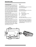
Page 6: ...s well as for trouble shooting Simultaneously to measurement the instrument TELARIS LOOP determines by calculation the short circuitcurrent Theshort circuitcurrentmust be known to guarantee that an ex...

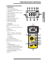
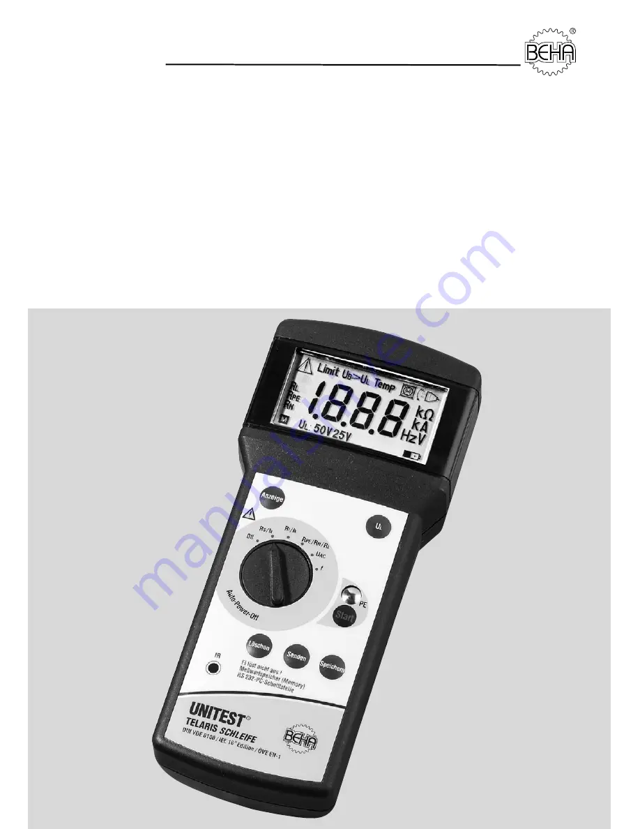
Page 7: ...for mains lead Test lead 14 LCD 15 Key Vc UL 50V 25V 25V for medical and agricul tural uses 16 Contact electrode 17 Measurement function switch off ZL IPSC Loop impedance short circuit current RI IPSC...

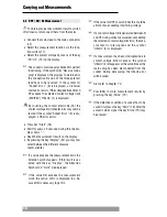
Page 8: ...e mains lead to the mains connector 13 Select the measurement function R via the fun ction switch 17 Connect the test cables mains plug to UUT socket by respecting correct polarity Set a voltage conta...

Page 9: ...ement results switch off all loads or disconnect them from the mains Connect the mains lead to the mains connector 13 Select measurement function via the function switch 17 Select contact voltage limi...

Page 10: ...ressing the key Display 23 you may now select between the different measure ment variables If a value exceeds the measurement limit the Attention symbol appears If this result is sel ected with the ke...

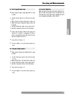
Page 11: ...t the measure ment instrument from UUT Also refer to chapter 7 0 No possibility to store the measurement re sults 6 5 Frequency Measurement Never apply tvoltages exceeding 300V to input sockets Connec...

Page 12: ...ceeded Contact voltage limit 50 V Resistance measurement Zl Ipsc ZL 2 88 Contact voltage limit 50 V Resistance measurement Zl Ipsc RL excessive 19 99 Measurement is interrupted Contact voltage limit 5...

Page 13: ...surement result by pressing key Store 19 Upon completion of storing a short signal is au dible and the symbol M 11 appears in the display for memory location In case of a full memory the symbol M blin...

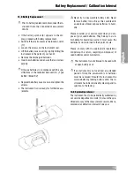
Page 14: ...rom the OFF position to the de sired function If the Battery is almost dead the symbol 8 appears in the indication The piece of equipment works furthermore however without claim on retention of the sp...

Page 15: ...tery cells Never throw a battery into a fire as this could lead to an explosion Never expose batteries to humi dity Please consider your environment when you dis pose of your used batteries They belon...

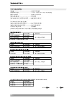
Page 16: ...01 Ohm 20 199 9 Ohm 0 1 Ohm 5 rdg 5 Digit 200 Ohm 1 999 kOhm 1 Ohm Internal Resistance RI Range Resolution Tolerance 0 05 19 99 Ohm 0 01 Ohm 5 rdg 5 Digit Resistance Neutral Conductor RN Range Resolu...

Page 17: ...z 0 1 Hz 1 rdg 2 Digit 400V RI 1 M Contact voltage detection UL 25V 25V 5 15 UL 50V 50V 5 15 For large mains voltage fluctuations during measurements the measurement error may increase Auto power off...

Page 18: ...18...

Page 19: ...oumis un contr le technique permanent Ces m mes quipements de contr le sont calibr s r guli rement l aide d appareils de r f rence calibr s selon les di rectives et normes en vigueur dans les laborato...

Page 20: ...e with unda maged warranty label Any damage due to dropping or incorrect handling are not covered by the war ranty If the instrument shows failure following ex piration of warranty our service depart...

Reviews: