background image


VERSAMET 4 INVERTED METALLURGICAL MICROSCOPE   


UNITRON


73 Mall Drive, Commack, NY  11725  •  631-543-2000  •  www.unitronusa.com 

11


ASSEMBLY

 (continued)


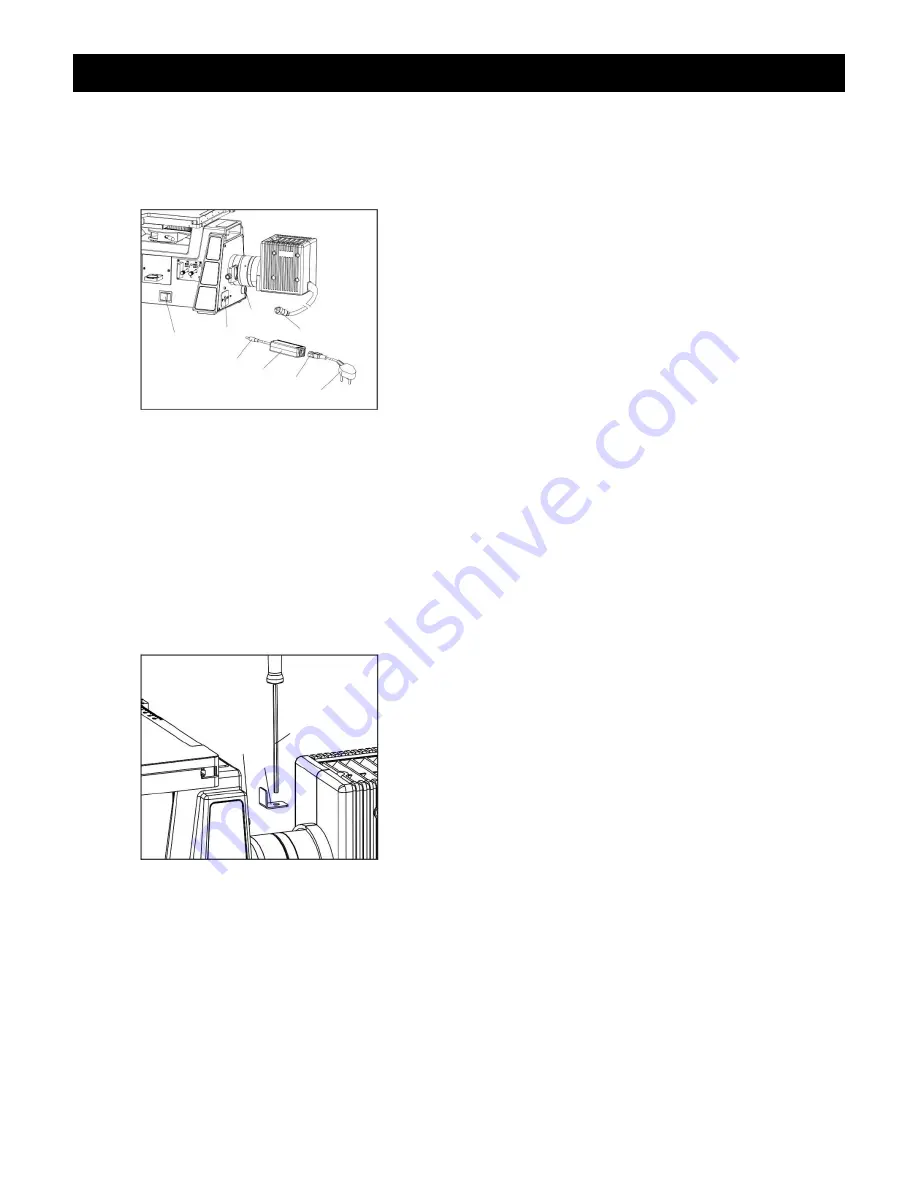
Connecting the Illuminator  
& Power Cords 

(Fig. 9)


Make sure the power switch 

① 

is set to “OFF”.   


Insert the plug 


of the illuminator into the “Output” 

socket 

 on the back of the microscope by aligning 

the notches on the plug with the two pegs on either 
side of the socket and then slide it on until it clicks 
into place. 


Insert the plug 

 of the external power supply 


into the 

“Input” socket on the back of the microscope 

with the flat side of the plug facing down.   
 
Insert the female end 

 of the power cord into the 

three pronged socket on the external power supply. 
 
Plug the other end 

 into a grounded (3-prong) 

outlet.  
 

NOTE

Always use the power cord that is provided 

with your microscope; using a different power cord 
may damage your microscope. Should you need a 
replacement, contact your authorized UNITRON 
dealer or call UNITRON at 1-631-543-2000 for a 
dealer nearest you.   


Storing the Hex Screwdriver 

(Fig. 10)


For convenience, you can store the hex screwdriver 

 for your microscope in the magnetic 

“L” mount 


provided. 
 
The mount can be attached to the magnet 

 on the 

back of the microscope with the hole positioned as 
shown.   
 
The hex screwdriver can then be inserted into the 
mount’s hole as shown for storage. 

Fig. 9 

Fig. 10 


Summary of Contents for Versamet 4

Page 1: ...73 Mall Drive Commack NY 11725 631 543 2000 P 631 589 6975 F www unitronusa com info unitronusa com Versamet 4 INVERTED METALLURGICAL MICROSCOPE MANUAL ...

Page 2: ......

Page 3: ...NT DIAGRAMS 5 6 ASSEMBLY DIAGRAM 7 DETAILED ASSEMBLY 8 11 OPERATION ILLUMINATION 12 SELECTING THE LIGHT PATH 13 FOCUSING 13 FOCUSING TENSION 14 INTERPUPILLARY DISTANCE 14 EYEGUARDS 14 FIELD DIAPHRAGM 15 APERTURE DIAPHRAGM 15 BRIGHTFIELD DARKFIELD 16 POLARIZER 16 MOUNTING A MICROSCOPY CAMERA OPTIONAL 17 DIC COMPONENTS OPTIONAL 17 18 REPLACING THE LAMP 18 TROUBLESHOOTING 19 20 MAINTENANCE 21 SERVICE...

Page 4: ...ferent input voltage other than indicated will cause severe damage to the microscope CARE AND MAINTENANCE 1 Do not attempt to disassemble any component including eyepieces objectives or focusing assembly 2 Keep the instrument clean remove dirt and debris regularly Accumulated dirt on metal surfaces should be cleaned with a damp cloth More persistent dirt should be removed using a mild soap solutio...

Page 5: ... microscope in dusty surroundings or in high temperature or humid areas as mold and mildew will form Carefully remove the microscope from the EPE foam container by its arm and base and place the microscope on a flat vibration free surface Check the components against the following standard configuration list Stand which includes the supporting arm trinocular viewing head and focusing mechanism Eye...

Page 6: ...ad Light Path Selection Slider Coarse Fine Focus Adjustment Knobs Eyepieces Metal Stage Insert Plate Camera Photo Port Mechanical Stage Color Filter Slider Tension Adjustment Collar Hex Screwdriver Lock Screw X Y Axis Stage Control Knobs Illuminator On Off Power Switch Aperture Diaphragm Lever Field Diaphragm Lever Polarizer Slot Light Intensity Control Knob ...

Page 7: ...AMET 4 INVERTED METALLURGICAL MICROSCOPE UNITRON 73 Mall Drive Commack NY 11725 631 543 2000 www unitronusa com 6 COMPONENTS DIAGRAM Objective Nosepiece Nosepiece Ring Brightfield Darkfield Lever Eco Button ...

Page 8: ...sembly Use the 1 5mm and 2mm hex wrenches that are supplied with your microscope when required Be sure to keep these wrenches for changing out components or making adjustments When assembling the microscope make sure that all parts are free of dust and dirt and avoid scratching any parts or touching glass surfaces Illuminator Nosepiece Objectives Metal Stage Insert Plate Stage Clips Eyepieces Filt...

Page 9: ...he lowest magnification objective onto the nosepiece opening then rotate the nosepiece clockwise and thread the other objectives from low to high magnification NOTE Always rotate the nosepiece by using the knurled nosepiece ring Fig 3 Keep the dust cap on any unused nosepiece openings to prevent dust and dirt from getting inside NOTE Clean the objectives periodically When viewing a sample focus th...

Page 10: ...tive Installing the Stage Clips Fig 6 Remove the clip from the column and screw the column into one of the holes on the stage Secure the column to the stage with the screw Then slide the clip onto the column facing toward the user Repeat for the other stage clip Installing the Eyepieces Fig 7 Remove the eyetube caps and insert the eyepieces into the eyepiece tubes Lock in the eyepieces using the s...

Page 11: ...ert a filter into the filter slider position the rounded side down and simply slide the filter into place NOTE be sure to keep the filter slider in an upright position as the filters when inserted do not click into place and can slide out if the slider is turned sideways or upside down To insert the filter slider into the filter slot you must remove one of the end screws by turning it counterclock...

Page 12: ... the plug facing down Insert the female end of the power cord into the three pronged socket on the external power supply Plug the other end into a grounded 3 prong outlet NOTE Always use the power cord that is provided with your microscope using a different power cord may damage your microscope Should you need a replacement contact your authorized UNITRON dealer or call UNITRON at 1 631 543 2000 f...

Page 13: ...rning the light intensity control knob clockwise to increase brightness Turn counterclockwise to decrease brightness ECO Economy Setting The Versamet 4 is equipped with an auto shut off feature or ECO mode to preserve the life of the bulb ECO mode activates when the microscope is unattended for thirty 30 minutes and turns the illuminator off It will reactivate and turn the illuminator back on when...

Page 14: ...Adjusting the Focus Fig 13 14 To ensure that you obtain sharp images with both eyes since eyes vary especially for those wearing glasses any eyesight variation can be corrected in the following manner Set both diopter collars to 0 by aligning the line on the eyepiece with the line on the diopter collar Using your left eye only and the lowest magnification objective 5x or 10X focus your specimen by...

Page 15: ...men Rotate the eyetubes around the central axis until the fields of view of both eyetubes coincide completely A complete circle should be seen in the viewing field when viewing the specimen slide An improper adjustment will cause operator fatigue and will disrupt the objective parfocality Where the on the eyepiece tube lines up with the interpupillary distance scale that is the number for your int...

Page 16: ...ment If the field diaphragm needs to be adjusted adjust the right and left centering screws using the hex screwdriver until the field diaphragm is centered in the field of view Using the Aperture Diaphragm Fig 20 21 The iris diaphragm determines the numerical aperture N A of the illumination system in bright field observation When the N A of the objective and the illumination system match you can ...

Page 17: ...le Polarizer Fig 23 The simple polarizer includes the polarizer and analyzer To use remove the dust plug from the polarizer slot and insert the polarizer slider into the slot as shown The polarizer is moved into the light path when you hear it the second click NOTE when using the polarizer remove the color filter slider There are two analyzers one fixed and the other 360 rotatable analyzer To use ...

Page 18: ...efer to page 13 Slide the light path selection slider to the left to the IN position This will send 0 of the light to the binocular viewing head and 100 to the top photo port for HDMI digital imaging and documentation Using the DIC Components Fig 25 While in brightfield observation focus a specimen with the 10x or 20x objective Push the polarizer and the analyzer into the light path and ensure the...

Page 19: ...g the Lamp Fig 26 27 The halogen lamp was installed by our factory technicians prior to shipment Should you need to change the lamp following the instructions below NOTE When handling the halogen lamp handle it only using lint free gloves cloth or tissue Touching the lamp with your fingers or other type of material can damage the bulb Turn the power switch to OFF and UNPLUG the microscope power co...

Page 20: ... or dust is visible in the field of view Dirt dust on the specimen Replace with a clean specimen Dirt dust on the eyepiece Clean the eyepieces The image is not clear Cover glass on the specimen slide Clean the specimen The specimen is not vertical to the objective Adjust it The nosepiece is not in the correct position Turn the nosepiece into the correct position The aperture diaphragm is not open ...

Page 21: ...nstalled correctly Install it correctly The lamp burns out Replace the lamp The light intensity is not enough The light intensity control knob is not set properly Adjust the light intensity control knob The wrong lamp is used Replace the lamp with the correct one The lamp keeps burning out The wrong lamp is used Replace the lamp with the correct one The lamp flickers or the brightness is not stabl...

Page 22: ...l and workmanship for a period of five 5 years for mechanical and optical components and one 1 year for LED bulb and electrical components from the date of invoice to the original end user purchaser This warranty does not cover damage caused in transit misuse neglect abuse or damage resulting from improper servicing or modification by other than UNITRON approved service personnel This warranty doe...

Reviews: