4.- PREPARATIONS BEFORE TO USE
- 25 -
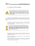
While measuring, the cables must not be stepped, moved or hit, because
the measurements could be altered, specially when measuring high-
quality insulations, due to the piezoelectric effect of the cable and the
weak measured currents. If it is possible, put these cables parallel and
nearest between them to avoid interferences.
If the shell of the machine to be analyzed is grounded, a check should be
made to ensure that this is the same ground as the one of the PC supply
and the measuring unit. To accomplish this, join these two points with a
plaited cable of adequate cross-section.
ALL THE GROUNDS USED
IN TESTING SHOULD BE INTERCONNECTED
.
- Connection of UM2B equipment to electrical mains.
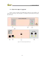
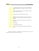
This connection is accomplished by running the power cable from (5) to a
mains socket. The supply voltage should be checked to ensure that it is within
the operating limits (see chapter 9: Specifications) and a check should made
to ensure that the socket has an operative ground.
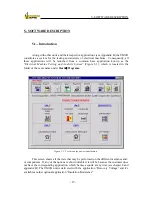
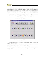
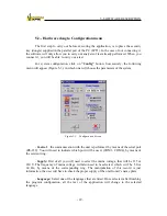
Once the different parts of the equipment have been connected, the PC should be
switched on and the control software executed. Following this, it will be sufficient to follow
the instructions as they appear on the PC screen. Consequently,
the UM2B unit should be
turned on when this software so requires
(4).
THE UM2B UNIT SHOULD NOT BE TURNED ON UNTIL
THIS IS INDICATED BY THE CONTROL SOFTWARE.
WARNING:
If the equipment is used outside manufacturer‟s
specifications, the security could be altered.
Summary of Contents for UM2B
Page 2: ......
Page 67: ...5 SOFTWARE DESCRIPTION 65 Figure 5 46 a First page of the report Recovery Voltage ...
Page 68: ...5 SOFTWARE DESCRIPTION 66 Figure 5 47 a Second page of report Recovery Voltage ...
Page 69: ...5 SOFTWARE DESCRIPTION 67 Figure 5 48 Third page of report Recovery Voltage ...
Page 70: ...5 SOFTWARE DESCRIPTION 68 Figure 5 46 b First page of the report Insulation Resistance ...
Page 71: ...5 SOFTWARE DESCRIPTION 69 Figure 5 47 b Second page of the report Insulation Resistance ...
Page 87: ...8 TECHNICAL SUPPORT 85 Description of fault Materials returned on of of the year Table 8 1 ...
Page 95: ...APPENDIX B CONTROL SOFTWARE 93 APPENDIX A CE CONFORMITY DECLARATION ...

